Automotive Power Electronics Hub
Automotive power hub: protect the vehicle supply and control inputs, design lighting, motor and drive circuits, and check qualification evidence.
50 guides
Follow the guides for the part of the vehicle you are working on: the supply rail, control input, lighting circuit or electric drive. Start with the event or load, then read the component, qualification and thermal checks that apply to it.
Jump to the article collection
Automotive power electronics begins with the vehicle supply environment
Vehicle electronics must manage energy while the surrounding electrical conditions change. A battery rail feeds lighting, control units, motors and communication interfaces, but the voltage at a module is shaped by wiring, switching loads, charging behavior and connection events. Different vehicle systems operate at different voltage levels, and an auxiliary circuit must not be confused with a high-voltage traction circuit. Define the actual electrical boundary of the module before selecting its diodes, switches or protection devices.
This hub connects automotive semiconductor topics by function: protecting a supply, converting power, controlling a load and checking the evidence behind a component choice. It serves readers learning how a vehicle electrical system works as well as engineers and buyers following a particular design. The practical starting question is where the part sits. The same device family can serve several roles, but the stresses and acceptance criteria depend on the circuit around it.
Separate reverse connection, reverse current and overvoltage
Reverse-battery protection addresses an incorrectly connected supply. Reverse-current blocking prevents energy from flowing back through a path when the relative voltages change. Overvoltage protection addresses an input that rises above the permitted operating range. These functions can overlap in a circuit, but they are not equivalent. A design that handles one condition does not automatically handle the others, especially when startup, shutdown and disconnected loads create additional current paths.
A series diode provides a straightforward polarity-dependent path but introduces forward loss. MOSFET-based protection can reduce conduction loss when appropriately controlled, while adding gate-drive and operating-state requirements. A TVS or other clamp can help manage specified transients, but its voltage window and energy path must fit the application. Choose the architecture from the complete input requirements rather than from a single comparison of diode drop and MOSFET resistance.
Follow energy through lighting, motors and auxiliary converters
An LED lighting module controls current through the emitters and must manage heat generated in both the LEDs and the driver. Rectifiers, switches and clamps support that function in different positions. A motor driver adds inductive energy and commutation paths; the current needs somewhere to flow when a switching device changes state. Whether that path is an external diode, a body diode or an actively controlled switch affects the resulting losses and voltage stress.
Auxiliary DC-DC conversion connects rails with different voltage and power requirements. Its semiconductor selection depends on topology, duty cycle, switching behavior, fault protection and available cooling. Devices should be compared at the operating conditions of their particular position. A MOSFET suitable for a low-voltage body module is not selected by the same shortlist as a device in an isolated high-voltage converter, even when both are described broadly as automotive power components.
Charging and traction have distinct semiconductor jobs
An electric vehicle contains several power-conversion blocks. The traction inverter converts battery energy into controlled motor currents, the onboard charger converts an external AC supply into battery-charging power, and other converters support auxiliary loads. DC charging moves much of the conversion task into external equipment. These differences explain why the phrase vehicle power semiconductor covers several device classes and several very different electrical environments.
Silicon, silicon carbide and gallium nitride should be compared within an identified conversion stage. Voltage blocking, switching loss, drive requirements, thermal design and implementation maturity all influence the decision. A demonstration in one architecture is not evidence that every vehicle application should change technology. Begin with the efficiency and operating requirements of the stage, then examine whether the proposed device and supporting circuitry can meet them across the intended mission profile.
Qualification evidence belongs to the exact part
Automotive qualification documentation concerns a defined product and its stated scope. It does not by itself establish that a complete module meets every vehicle requirement, nor does a family name prove that every ordering variant carries the same status. Match the exact manufacturer, part number, package and documentation when reviewing a candidate. If the application depends on a particular qualification or production-control requirement, request evidence tied to the supplied device rather than relying on a general catalog description.
The circuit still needs application validation. Temperature cycling, sustained operation, transient exposure, mounting and mechanical conditions can interact in ways that a component headline does not describe. A device may satisfy its own published limits yet fail to meet a module's functional requirements because of layout or control behavior. Keep component qualification, supplier documentation and system-level verification as separate pieces of evidence that support one final decision.
Review the whole module during a component change
Suppose a body-control module receives an alternative power MOSFET because the original is unavailable. The review must preserve pin assignment, drive compatibility, load handling and protection behavior, along with the documentation required for that application. A matching voltage and package are only initial filters. Checking the completed module at its relevant operating states establishes whether the alternative preserves the intended function. Record any changed gate components, firmware timing or mounting details with the approval so that production and later repairs use the same verified configuration.
Diagnose with operating conditions and preserve the evidence
When a vehicle module fails, record the symptom, supply state, connected load and relevant temperatures before replacing components. Check wiring, grounds and connectors as well as the visibly damaged part. A failed clamp may indicate a supply event, while a hot power switch may reflect inadequate drive, excess load current or a poor heat path. The replacement needs to address the identified mechanism, not merely restore continuity on the bench.
For sourcing, retain the full orderable code, current datasheet, approved package and qualification records alongside the circuit requirements. For design and repair, add waveforms and measurements that explain why the choice works. Use the grouped articles below to move from vehicle-system basics into protection, lighting, motor control, charging and component verification. Each narrower guide should help resolve a specific question within the electrical boundary you have already defined.
Protect the vehicle supply and control inputs
These guides cover the supply conditions and protection decisions at the entry to vehicle electronics.
ASMBJ28CA: 600 W Automotive TVS in SMB for Lighting Drivers
The ASMBJ28CA is a 28 V, 600 W transient voltage suppressor in an SMB (DO-214AA) package from Good-Ark, positioned on the site for automotive lighting-driver applications. The site publishes the class and the…
Automotive ECU Power Design: From 12 V Transients to Low-Voltage Rails
An ECU power tree runs from the battery’s 12 V through protection, buck converters, and down to 3.3 V logic rails, and every stage has a rectifier or protection diode with a different job. This guide walks the…
Automotive Grade Rectifiers: Applications, Ratings and Validation
A diode that survives on a bench can still run too hot inside a sealed vehicle controller. Choosing an automotive grade rectifier means matching its electrical characteristics, package and qualification to a…
Automotive MOSFET Design-In: AEC-Q101, Load Dump, SOA, and Mission Profiles
Key Takeaways AEC-Q101 is the entry ticket, not the whole story: the mission profile (temperature cycles, load dump, SOA) decides whether the MOSFET survives a decade in a vehicle. Load-dump and transient…
Automotive Schottky Rectifier: Selection, Losses and Protection
An automotive Schottky rectifier is a Schottky diode selected for a defined role in vehicle electronics and supported by the required device qualification. It can reduce forward-conduction loss in converter,…
AWSS10H100: A 10 A, 100 V Schottky for ECU and Lighting Power
The AWSS10H100 is a 10 A, 100 V Schottky barrier rectifier in an eSGC (TO-277) package from Good-Ark, positioned on the Good-Ark site for automotive lighting and ECU power. It is the top of the AWSS current…
AWSS5H60: A 5 A, 60 V Schottky for Automotive Lighting and ECU Power
The AWSS5H60 is a 5 A, 60 V Schottky barrier rectifier in an eSGC (TO-277) package from Good-Ark, positioned on the Good-Ark site for automotive lighting and ECU power. The site publishes the ratings, the…
Choosing a TVS for 24 V Inputs: Industrial and Automotive Rail Protection
The 24 V rail in an industrial cabinet and the 24 V rail in a truck look alike on a label and behave very differently under transients. The industrial rail carries switching spikes from contactors and motor…
Co-Designing Rectifier and TVS for 12 V ECU Input Protection
The 12 V ECU input protection is a three-layer chain: the TVS clamps the transient, the rectifier blocks the wrong polarity and the residual, and the filter absorbs what passes. This guide covers the threat…
Cranking Voltage Dips and Starter Loads: How the 12 V Rail Diodes Stay Alive
Cranking is the two-second blackout of the 12 V rail. The starter motor pulls hundreds of amps, the battery voltage collapses toward 6-8 V, and every module on the rail — the ECU, the lighting, the pump —…
ECU Input Protection: From ISO 7637 Pulses to the Last Diode Before the MCU
An ECU input is a guard chain, not a single component. From the connector, the voltage travels through a TVS, a series diode, a filter, and finally lands on the pin of the MCU — and each guard stops a…
How do TVS diodes solve automotive load dump issues?
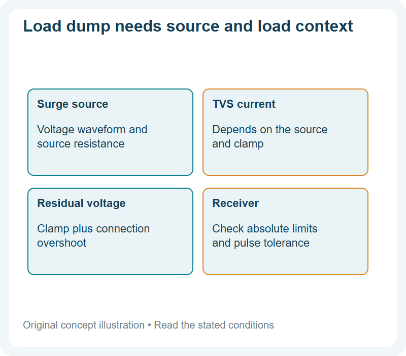
Load dump delivers hundreds of joules over tens of milliseconds. What ISO 16750-2 test A actually specifies, and why a 600 W TVS is not the answer.
Load Dump De-Mystified: The 87 V Spike, Why It Happens, and How Components Survive
Every automotive engineer has heard of load dump, and most have heard only one number: 87 V. Fewer can explain why the rail spikes that high, why the spike has an energy and not just a voltage, and what…
Load Dump Explained: The 87 V Spike Your Car Electronics Must Survive
Load dump is the reason automotive electronics are specified and tested differently from consumer electronics. It is not a fault and it is not rare in the sense of being impossible: it is a normal consequence…
Reverse Polarity Protection in Vehicles: Diodes, Ideal Diodes, and the Fuse-Blow Trap
A reversed battery connection is one of the most common and most destructive mistakes in vehicle electrical work, and the irony of the standard protection is that it can make the failure worse. Connect a…
The 12 V Automotive Rail: Transients It Sees, Components That Survive Them
The 12 V automotive rail is the one power bus nearly every electronic module on a car shares, and it is also the least “regulated” rail an engineer will ever design against. Over a single day of driving, the…
TVS Placement and Layout for Automotive Lighting Lines
The TVS’s placement decides whether the datasheet’s clamp is the circuit’s clamp: close to the connector, short to ground, and a small loop are the rules, and the parasitic inductance is the enemy. This guide…
Design lighting, motors and electric drives
Follow the reading for the load you need to drive. Keep the operating duty and device choice in the same review.
AMBRP5100: 5 A, 100 V Schottky in PDFN56 for T-BOX and Lighting Control
The AMBRP5100 is a 5 A, 100 V Schottky barrier rectifier in a PDFN56 package from Good-Ark, with 0.70 V typical forward drop at 5 A, a 120 A surge rating, and 3 °C/W junction-to-case resistance. It targets…
Automotive Lighting Driver Rectifier Design: Efficiency in a Sealed Lamp Module
An automotive lamp module seals its electronics in a small, hot housing, and the rectifier—often the smallest component—carries the efficiency and thermal story. This guide covers the driver architectures, the…
Automotive Lighting Electronics: From Halogen to Matrix LED Power Needs
Automotive lighting moved from halogen to LED and now to matrix and adaptive systems, and the Good-Ark device families are part of the power-stage roadmap, and each step changed the power stage: more current,…
Automotive Lighting: Elevating Vehicle Efficiency With Good-Ark
Automotive lighting parts are qualified, not just specified. What AEC-Q101 evidence to request, and how a lamp module’s heat budget decides the device.
AWSS10H60: 10 A, 60 V Schottky for High-Current Automotive Lighting
The AWSS10H60 is a 10 A, 60 V Schottky barrier rectifier in an eSGC (TO-277) package from Good-Ark, positioned for high-current automotive lighting. It is the 60 V cell of the 10 A AWSS row, and its full…
AWSS5H100: 5 A, 100 V Schottky for Automotive Lighting Modules
The AWSS5H100 is a 5 A, 100 V Schottky barrier rectifier in an eSGC (TO-277) package from Good-Ark, positioned on the site for automotive lighting modules. It is the 100 V cell of the 5 A AWSS row, and its…
Electric Power Steering Rectifier Design: Surviving the Steering Load Profile
Electric power steering runs a motor whose load swings from a light cruise current to a full stall current in seconds, and the freewheeling diode must survive both. This guide covers the load profile, the…
Electric Power Steering: The Load-Pulse Profile a Diode Must Survive
Electric power steering (EPS) is the rare automotive load that goes from gentle assist to full stall within seconds. One moment the motor is drawing a few amps to help a light turn; the next it is holding a…
LED Lighting Drivers in Cars: Where the Diode Fails First and How to Design Against It
An automotive LED lamp module is a small, sealed electronics box that runs hot, vibrates, and is expected to outlive the warranty with no maintenance access. The diode is usually the first part to give up…
MOSFETs and IGBTs in Electric Drives: Voltage Class, Frequency, and the Traction Trade
An electric vehicle is not one power stage; it is a map of them. A traction inverter, a DC-DC converter, an on-board charger, a set of auxiliary loads — each stage runs at a different voltage, frequency, and…
Solder Joint Reliability for TO-277 in Automotive LED Modules
In an automotive lamp module, the solder joint under the TO-277 exposed pad is the weakest connection: thermal cycling and vibration fatigue it long before the die fails. This guide covers the mechanism, the…
GaN Traction Inverters Reach Vehicle Demonstrators: Status Check vs SiC Mainstream
Distinguish GaN vehicle demonstrators from production traction systems and compare their role with SiC.
How Does an Electric Car Charge? AC, DC and What Happens Inside
Compare AC and DC vehicle charging and locate the hardware responsible for converting power.
Inside an Electric Car: Where the Power Electronics Sit
Locate the battery, inverter, charger and DC-DC converter in an electric vehicle power architecture.
Check automotive parts and qualification evidence
Use the component and qualification guides to connect a proposed part to the conditions in the application.
60 V vs 100 V Schottky for Automotive Loads: Margin Has a Price
The 100 V Schottky class buys more transient margin than the 60 V class, and it charges for it: higher forward drop at a given current and a different leakage picture at the operating point. This guide maps…
AEC-Q101 Explained: What Automotive Grade Really Means
“Automotive grade” is one of the most misused phrases in component buying. It does not mean better quality in general, it does not mean the part is more accurate, and it does not describe a single test. It…
AEC-Q101 in Practice: How to Verify an Automotive Part Beyond the Datasheet
“AEC-Q101 compliant” is one of the most reassuring phrases on a semiconductor datasheet and one of the least examined. The stamped claim promises a part survived a specific set of accelerated stress tests, but…
AMBRB30200CT: 30 A, 200 V Schottky in D2PAK for OBC
The AMBRB30200CT is a 30 A, 200 V common-cathode Schottky dual diode in a D2PAK package from Good-Ark, with 0.84 V typical forward drop per die at 15 A and a 200 A per-die surge rating. It targets the 200…
Automotive Applications: Powering Safer, More Efficient Vehicle Electronics
Automotive electronics selection guide: what AEC-Q101, ISO 26262 and IATF 16949 require, and which device answers each electrical disturbance.
Automotive-Grade vs Commercial-Grade Semiconductors: A Selection Framework
Automotive grade means the part is qualified to the automotive expectation—the AEC-Q101-style stress set and the vehicle temperature range—while commercial grade is qualified to less demanding conditions. The…
Body Control Modules: Power Budgets, Wake-Up Currents, and the Diode Roles in Between
A body control module (BCM) is a list of loads with a power budget attached: lights, locks, wipers, and relays, each with a peak and an idle current, all sharing one rail. The diode plan follows that budget.…
EPS: Efficient Power Rectification for Modern Power Electronics
An EPS power chain loses watts, not percentages. How to model rectification loss on a 12 V or 48 V steering path and pick a device that stays cool.
Good-Ark Automotive Portfolio: Qualified Discretes by Function
An automotive program does not buy a diode; it buys a part with qualification evidence, a mission-profile fit and a traceable supply chain. Good-Ark’s automotive discrete portfolio spans rectifiers, Schottky…
OBC Architecture Trends: Bidirectional, High-Voltage, and Power-Dense
The on-board charger is moving in three directions at once: bidirectional power flow, higher bus voltages, and higher power density. Each trend changes the rectifier story, and this guide traces the three…
OBC Diode Design: PFC and DC-DC, Two Mindsets, One Efficiency Number
The on-board charger (OBC) is a box with two very different power stages inside it, and the efficiency number on the datasheet hides both of them. Up front, the PFC stage wants speed — fast diodes that can…
T-BOX Power Design: Quiescent Current and Wake-Up Bursts in Telematics
A telematics box is always on: its standby power is counted in milliwatts and its wake-up communication bursts in amps, and the rectifier sits in both regimes. This guide covers the quiescent budget, the burst…
The AWSS Family by the Numbers: Matching 5/10 A and 60/100 V Schottkys to Automotive Loads
The AWSS family answers most automotive Schottky selection questions with a single table. Four parts — built from 5 A or 10 A current classes and 60 V or 100 V voltage classes — cover the lighting, ECU, and…
The AWSS Family: Matching 5/10 A and 60/100 V Parts to Your Automotive Load
The AWSS family covers the automotive lighting and ECU domain with four parts in one footprint: 5 A and 10 A, crossed with 60 V and 100 V, all in eSGC (TO-277). This guide maps the lineup, matches the load,…
Thermal Management for a 10 A Automotive Rectifier: A Worked Case
Ten amps continuous in a sealed automotive housing is a thermal case study: the forward-drop loss at temperature, the junction calculation, and the copper-and-housing countermeasures. This guide walks the…
TO-277 vs SMB/SMA: The Power Rating Gap in Automotive SMDs
SMD power packages look interchangeable and are not: the capability band runs from SMA through SMB and SMC to TO-277, and each rung carries a different current and a different thermal contract. This guide…
What Is an Automotive ESD Suppressor?
Device ESD immunity is quoted to IEC 61000-4-2, vehicle testing to ISO 10605, and parts to AEC-Q101. What an automotive ESD suppressor must prove.
Automotive Semiconductor Report 2026
2026 automotive discrete and power-device demand themes for design and sourcing teams.
EV Power Electronics Industry Report
EV traction, OBC, and DC-DC power-electronics themes that drive discrete selection.
Soft Guidance in Auto Chips: What Discrete Diode and MOSFET Buyers Should Watch
Translate automotive chip-demand signals into lead-time, stock and qualification checks for discrete buyers.
Automotive Bridge Rectifier Module: A Practical B2B Buying Guide
Specify an automotive bridge module by voltage, current, surge, mounting and qualification evidence.
Need help with a particular circuit?
Include the circuit position, operating conditions and the part number or marking when you contact Good-Ark technical support.
Recommended
 Thyristor vs Triac: AC Control Devices Compared for BeginnersKnowledge
 Synchronous Rectification vs Schottky: A Beginner Decision FrameKnowledge
 Optocoupler How It Works in Isolated SMPS FeedbackKnowledge
 Soft Start and Inrush: Diode Ifsm Beside Control TricksKnowledge
 Flyback Transformer Basics for Discrete Learners (Diode-Side Focus)Knowledge
 SMPS Rectifier Diode Selection: Primary vs Secondary JobsKnowledge