Optocoupler How It Works in Isolated SMPS Feedback
See how an optocoupler carries isolated SMPS feedback. Follow the LED and transistor signal, CTR limits, bias requirements, loop stability and verification.
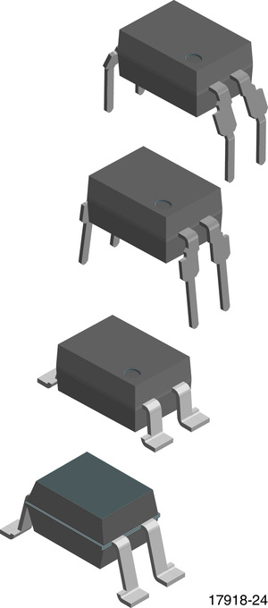
An optocoupler can help regulate a power supply without delivering useful load power across its isolation barrier. The magnetic power stage transfers the energy; the optocoupler carries information that tells the controller whether to increase or reduce that transfer.
That distinction matters when reading a low-cost-looking feedback circuit. Its design effort includes LED bias, transistor headroom, reference current, loop compensation, and isolation layout. Counting one small package misses most of the work. No component prices are assumed in this explanation.
Optocoupler: how does it work in SMPS feedback?
In a common isolated SMPS feedback circuit, an output-sensing network changes current through an optocoupler’s LED. Light crosses an insulating barrier and changes the current available from its phototransistor. The primary controller interprets that signal to adjust power transfer. Correct regulation depends on circuit polarity, bias, current transfer ratio, and loop compensation.
Follow the signal from output error to switching command
First identify the secondary-side voltage divider and its reference or error amplifier. A common implementation uses a TL431-type adjustable shunt regulator. Its reference terminal senses a divided output voltage, while its cathode circuit influences the optocoupler LED current. The surrounding resistors and compensation network define the behavior.
Next cross the barrier optically. The phototransistor does not share the LED-side return conductor. A primary-side bias network converts its current into the signal expected by the controller. In many circuits, a rising output increases LED current, and the resulting primary-side signal reduces delivered power. Check the actual controller polarity before using that sequence as a rule.
Finally close the loop: reduced power lets the output return toward its target. TI’s optocoupler-bias article discusses a common implementation. The SMPS rectifier selection guide concerns the separate power path, whose current the feedback system ultimately controls.
Budget the currents before counting components
The LED needs enough current for the receiving stage, but driving it harder is not a universal improvement. Current transfer ratio, CTR, is IC/IF expressed as a percentage under specified conditions. It varies with operating current, temperature, device grouping, and aging. Renesas explains those CTR dependencies.
For an illustrative static estimate, suppose the receiving circuit needs 0.5 mA and a supported minimum CTR at the relevant operating point is 50%. The ideal LED-current requirement would be at least 1 mA. This arithmetic is not a complete bias design: transistor voltage, LED forward drop, temperature range, reference current, and dynamic behavior remain to be checked.
Likewise, a TL431-type part needs its own operating headroom and current. Do not assume every variant has the same minimum current or pinout. Consult the exact TL431 product documentation and then the selected orderable device’s datasheet. A familiar family name is not a substitute for the actual circuit conditions.
Which parameters change the design effort?
| Parameter or requirement | Why it matters | Evidence to retain |
|---|---|---|
| CTR range | Changes available receiving current and loop gain | Group, test current, transistor voltage and temperature |
| LED bias and power | Consumes output-side current and affects operating point | Minimum and maximum current across source and load range |
| Transistor headroom | Limits useful signal swing and affects saturation recovery | Collector voltage and current in normal and transient states |
| Frequency response | Adds gain and phase behavior to the complete loop | Device data, compensation analysis and loop verification |
| Isolation implementation | Defines acceptable separation for the equipment | Exact component ratings, layout and applicable requirements |
These are engineering and verification costs, not a price quotation. A substitute with the same footprint can increase the required redesign if its CTR group, capacitance, or approved isolation characteristics differ. Avoid judging equivalence from the package alone.
Why does a brighter LED not guarantee a faster loop?
More phototransistor current can drive the receiving stage toward saturation, change available signal swing, or alter the dynamic response. The complete feedback network includes the power-stage response, controller, reference circuit, compensation, optocoupler, and sensing components.
Vishay’s CTR and switching-time note shows why transistor-output optocoupler timing must be evaluated with its load and operating conditions. A digital switching-time entry alone does not specify the stability of an analog power-supply feedback loop.
Common mistakes include copying compensation from another output capacitor, designing around typical CTR only, and replacing an analog-feedback optocoupler with an unrelated digital-output isolator. A correct DC output at one load does not demonstrate adequate transient response or stability across the operating range.
Verify the signal without bridging the isolation barrier
Begin with isolated power and the equipment’s stored-energy procedure. Confirm the LED polarity, phototransistor terminals, resistor values, and exact replacement group. An LED forward-voltage check can reveal some faults, but it cannot establish CTR, insulation integrity, or closed-loop behavior.
Energized testing on hazardous supplies requires qualified personnel and an appropriate measurement setup. Grounded instrument connections can unintentionally connect the two circuit returns. Use suitable probes and verified reference arrangements; Tektronix floating-measurement guidance explains the instrument issue. Never defeat protective earth to make a measurement.
Assess output startup, load steps, input variation, and the feedback signal’s headroom under defined conditions. Loop measurements and stability analysis require a suitable method and a person who understands the circuit. Intentionally opening feedback while operating can remove regulation and is not an appropriate beginner fault-finding shortcut.
Keep protection and power switching in their own roles
The optocoupler reports output error. The primary switch controls energy transfer; the rectifier directs current; a TVS diode handles its specified surge path. One function does not replace the others. Review discrete power-device roles when several unfamiliar symbols appear around the transformer.

Keep a reviewable feedback checklist
Record the sensed output, divider ratio, reference part, LED-current range, CTR evidence, phototransistor operating range, controller polarity, and compensation network. Add startup, no-load, full-load, temperature, and fault-response requirements. Keep isolation ratings and board separation requirements attached to the exact component and equipment design.
Other isolated systems, including PV inverter power stages, can use different sensing and isolation methods. Read the actual schematic before assuming every optical package performs this SMPS-feedback job. A clear signal path is the starting point for a defensible replacement or design review.
FAQ
Does an optocoupler regulate the output by itself?
No. It carries a signal across an insulating barrier. Regulation comes from the complete loop, including output sensing, a reference or error amplifier, the receiving circuit, the controller, and the power stage. A working optical link is necessary in a circuit designed around it, but it does not establish correct bias or stability. Check the actual schematic and component conditions before attributing an output problem to the optocoupler alone.
Is CTR a fixed gain that I can use at every LED current?
No. The specified CTR belongs to stated test conditions and often a particular device group. Operating current, transistor voltage, temperature, and aging can change the available transfer. Use applicable limits and curves for the selected part rather than one typical percentage. Check the receiving circuit’s current and signal swing as well, because a static current ratio does not describe the complete feedback loop’s dynamic behavior.
Can the same package guarantee a suitable replacement?
No. Package appearance does not establish the pin arrangement, CTR group, frequency behavior, LED requirements, or isolation characteristics needed by the circuit. Compare the exact original and replacement documentation, including applicable operating and safety conditions. Recheck bias and loop behavior when relevant parameters change. A physically fitting part may still leave insufficient signal range or change the response of the supply during startup and load transients.
Recommended
 Thyristor vs Triac: AC Control Devices Compared for BeginnersKnowledge
 Synchronous Rectification vs Schottky: A Beginner Decision FrameKnowledge
 Soft Start and Inrush: Diode Ifsm Beside Control TricksKnowledge
 Flyback Transformer Basics for Discrete Learners (Diode-Side Focus)Knowledge
 SMPS Rectifier Diode Selection: Primary vs Secondary JobsKnowledge
 Ohm’s Law for Diode Circuits: Drop, Dissipation, Sanity ChecksKnowledge