Automotive Bridge Rectifier Module: A Practical B2B Buying Guide
Updated: October 28, 2026 An automotive bridge rectifier module is often purchased as a mechanical and thermal assembly, not as four anonymous…
Updated: October 28, 2026
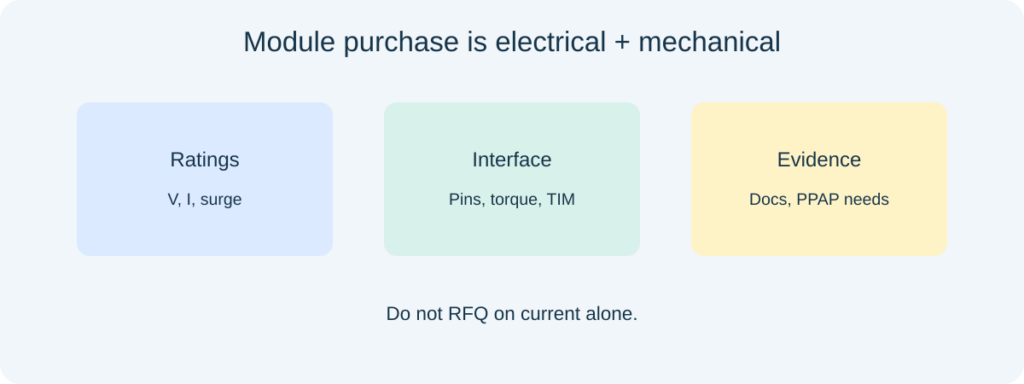
An automotive bridge rectifier module is often purchased as a mechanical and thermal assembly, not as four anonymous diodes. Buyers and power engineers need a clear RFQ language for voltage, current, surge, mounting, and documentation—especially when the module feeds vehicle or harsh-environment power stages rather than a benchtop experiment.
What an automotive bridge rectifier module is buying
You are buying a packaged four-diode (or related) bridge with defined terminals, insulation, and thermal interface for AC-to-DC or alternator-style rectification duties.
Discrete bridges on a PCB and press-fit or chassis modules solve different assembly and cooling problems. Mixing those categories in a cross-reference is a frequent sourcing error. For a general single-phase module primer, see what is a single-phase bridge rectifier module.
Public manufacturer documentation—such as ST’s automotive bridge rectifier diode documentation hub—shows how automotive-oriented lines are published with application-specific collateral. Use that as a model for the evidence you request, not as a claim that every bridge on the market carries the same qualifications.
Module versus discrete bridge: decision factors
| Factor | Module | Discrete bridge / four diodes |
|---|---|---|
| Thermal path | Often designed for a heatsink or chassis | Depends heavily on PCB copper |
| Assembly | Fewer solder joints; defined terminals | More placement freedom; more process variables |
| Service / replacement | Often field-replaceable as a unit | Usually board-level repair |
| Customization | Fixed outline and ratings menu | Easier to mix diode technologies |
General “how a bridge works” articles (Fly-Wing, HyperPhysics-style explainers) cover conduction paths well. They rarely explain when a module’s isolated baseplate or screw terminals are the real purchase reason. Put that mechanical need in the RFQ first sentence.

Which electrical ratings belong on the RFQ?
State repetitive reverse voltage, average output current, non-repetitive surge, and the thermal reference the current rating assumes.
TM Power Supply and similar selection articles emphasize calculating load current and allowing margin. For automotive or mobile power, also state the maximum expected input peaks and whether the load can stall or produce regenerative events that reverse energy into the DC bus. Derating for ambient under the hood or in an enclosed bay must be written numerically.
Kingtronics-style SMPS bridge guides highlight inrush with bulk capacitors—the same physics appears on vehicle accessory converters and industrial offboard chargers. If an NTC or active limiter is present, say so; surge demand on the bridge changes.
Automotive environment language without over-claiming
Vehicle electrical systems can impose load dumps, jumps, and cold-crank conditions that exceed ordinary appliance mains peaks. Refer to the OEM’s required standards and test plans by name when you know them. Do not label a part “automotive grade” in a blog RFQ template unless the specific qualification evidence is in hand.
Good-Ark’s public materials list automotive among application areas and show quality-system certificates on the company site; those statements describe company systems and published product directions. They are not a substitute for a part-specific AEC or OEM approval record. Ask for the exact documents your program file already requires.
Mechanical, thermal, and pinout checks
- Terminal map: AC inputs, DC+/DC−, sense or auxiliary pins if any
- Mounting: hole pattern, isolated vs non-isolated base, recommended torque
- Thermal interface material and maximum case or junction temperature in the duty cycle
- Creepage/clearance expectations for the working voltage
Digi-Key’s bridge rectifier selection discussions often stress package and current. Add isolation and torque for modules bolted to a chassis. A wrong pin map is more expensive than a slightly higher VF.

How do you compare two module quotes fairly?
Normalize voltage margin, thermal assumptions, and documentation scope before comparing price.
A cheaper module rated at a lower ambient or with a non-isolated base is not the same deliverable. Ask both suppliers to state losses or VF at the same current and temperature if efficiency matters to the vehicle energy budget. For Schottky-based automotive rectification in other circuit positions, see the automotive Schottky rectifier guide—that article covers diode technology choices that sometimes appear inside or beside bridge solutions.
Sampling and incoming checks
On samples, verify pin continuity of the four arms, insulation where claimed, and nameplate versus PO description. Thermal imaging under a controlled load is more informative than a cold multimeter diode-mode check alone. Keep the same heatsink and torque used in the application drawing.
Industrial Monitor Direct and other design notes remind readers that capacitor and diode selection interact; for modules, the external DC bus still sets ripple current and stress. Coordinate with the capacitor owner on the program.
Incoming inspection notes for modules
Record insulation resistance where the datasheet claims isolation, confirm marking against the packing list, and photograph the terminal orientation before first power-up. If the module uses a thermal pad, verify pad cleanliness and TIM thickness against the drawing. Failures that look “electrical” sometimes start as a dry thermal interface under vehicle vibration.
For programs that stock service spares, freeze a single mechanical revision in the AVL so field replacements remain interchangeable. A silent outline change that still carries a similar rating can break harness or bracket compatibility.
Where Good-Ark’s published scope helps
Good-Ark lists miniature bridge and rectifier families among its discrete offerings on en.goodark.com and cites automotive applications on its site. Use datasheets to confirm whether a given line is a PCB bridge, a module outline, or a related rectifier product—then map it to your mechanical need. Unverified “full automotive coverage for all bridges” claims do not belong in the article or the PO.
Frequently asked questions
Can I replace a chassis module with four SMD diodes to save cost?
Only after redesigning thermal, creepage, and service strategy. It is not a purchasing-only swap.
What surge rating should I request?
Use the inrush and fault currents from the application, not a generic multiple of average current copied from another project.
Do all automotive bridges need the same qualification file?
No. Follow the OEM or Tier-1 document list for that program. Do not assume one certificate covers every plant and part.
Is a higher VRRM always better?
Extra voltage margin can help, but package, VF, and thermal behavior may change. Compare at the same operating point.
Continue through this engineering topic
- What is a single-phase bridge rectifier module?
- How to choose the right power rectifier
- Automotive Schottky rectifier guide
- Protection diodes overview
Topic hub: Single-phase bridge rectifier module — related rectifier and automotive guides in this cluster.
Recommended
 Gate, Drain, Source: The Three Pins of a MOSFET Explained With a Water AnalogyKnowledge
 The Silicon Carbide Market in 2026: Capacity, Prices and AdoptionKnowledge
 What Is a TVS Diode? Surge Protection Explained SimplyKnowledge
 What Static Electricity Really Does to Your ElectronicsKnowledge
 Zener Diodes: Voltage Regulation, Circuit Protection, and ProcurementKnowledge
 Si MOSFET Power Switching for SMPS, PV Inverters, and Automotive DesignsKnowledge