Gate, Drain, Source: The Three Pins of a MOSFET Explained With a Water Analogy
Gate, drain, source explained: three names, three jobs, and one rule that prevents most wiring mistakes, because the gate is measured to the source.
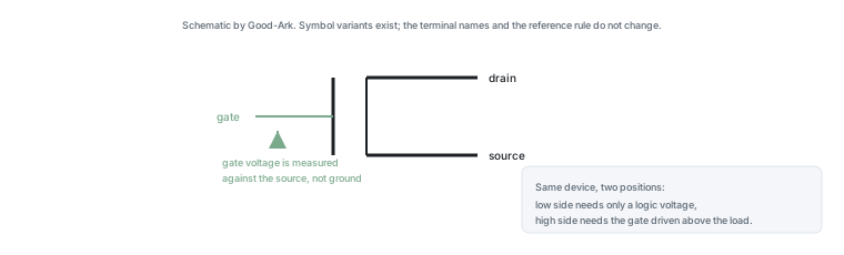
Most beginner wiring mistakes with a MOSFET come from one misunderstanding: the gate voltage is measured between the gate and the source, not between the gate and the circuit’s ground. Once that rule is clear, the three terminal names stop being arbitrary and start predicting what a circuit will do.
Last updated:
Three names, three roles
The gate is the control terminal, and it behaves electrically like a small capacitor: applying a voltage charges it, removing the voltage discharges it, and almost no current flows in the steady state. The drain and the source are the two ends of the switched path. In an n-channel device the channel opens when the gate is above the source, and current then flows from drain to source.
Two names cause most of the confusion. “Source” suggests a source of current, which invites the assumption that it is always the positive terminal. It is not: its name comes from the fact that it is the terminal to which the gate voltage is referenced, and the carriers in an n-channel device originate there. “Drain” suggests something being drained, which is closer, since it is where the controlled current enters. Our article on what a MOSFET is covers the mechanism behind that behaviour.
The water-tank model
Picture a tank of water with a pipe leaving the bottom, a valve in the pipe, and a handle on the valve. The tank is the supply, the pipe is the main current path, the valve is the channel between drain and source, and the handle is the gate. Turning the handle does not move water; it changes whether the channel is open.
The model earns its place because it also captures two things that trip people up. The handle’s position is measured relative to the pipe it controls, not relative to the floor — which is the gate-versus-source rule. And even a fully open valve has some friction, so water arrives at slightly lower pressure than it left the tank — which is the on-resistance and the heat it produces.
Gate: the control handle
The gate is separated from the conducting channel by a very thin insulating layer, so it looks like a capacitor to whatever drives it. That has three practical consequences. A gate left floating will hold whatever charge it accumulated, so a pull-down resistor is needed to define the off state. The driving circuit must supply a brief current to charge and discharge the gate capacitance at each transition. And the gate is easily destroyed by overvoltage, because the insulating layer is only nanometres thick.
The third consequence is why gate resistors, gate clamps and careful handling matter more for MOSFETs than for almost any other discrete device. A gate taken even briefly above its maximum rating fails permanently, and the failure is not always visible from the outside.
Drain and source: the main path
When the device is on, the path between drain and source presents a small resistance, and the current it carries produces heat in proportion to that resistance and the square of the current. When the device is off, the path is supposed to block — and here the direction of the applied voltage matters, because the blocking capability in the reverse direction is limited by the internal diode rather than by the channel.
That asymmetry is worth remembering when reading a datasheet: a MOSFET is not a symmetric switch. The voltage it can block depends on which way round it is connected, and the body diode provides a path in the other direction that the gate cannot close.
Why direction matters for N-channel
In an n-channel device operated normally, the drain is the more positive terminal and current flows from drain to source when the gate is above the source. Reverse the connection and the body diode conducts immediately, which means the device cannot block at all in that direction. This is why swapping drain and source in a circuit sometimes appears to work and sometimes destroys the switching behaviour entirely.
The reason the swap is sometimes survivable is that some devices are constructed so the two terminals are nearly symmetric in the on state. That is a property of particular designs rather than of the family, and it is not something to rely on. Treat drain and source as fixed unless the datasheet explicitly says otherwise.
Two further notes belong with the water model, because both cause real mistakes. The handle does not care what the rest of the circuit is doing; it only responds to the difference between itself and the pipe it controls. And the valve is not the only path in the system: the body diode acts like a bypass channel that opens in one direction whether the handle is turned or not, which is why a MOSFET cannot be assumed to isolate a load simply because its gate is at zero.
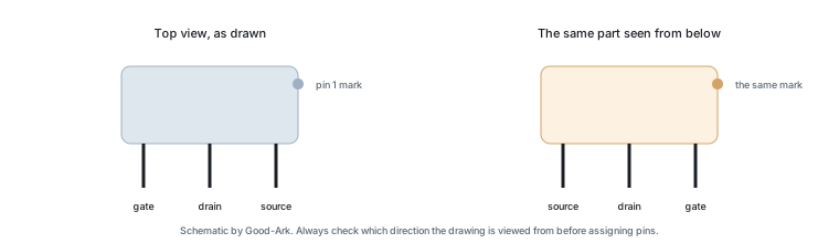
Reading a pinout drawing
A pinout drawing shows the package from a stated direction, usually the top, with the pins numbered. Three things are worth checking every time. Which direction the drawing is viewed from, because a bottom view mirrors the arrangement. Which pin is numbered one, since that convention is not universal across packages. And whether the diagram is describing the package or the electrical symbol, because the two are drawn in different orientations and beginners mix them up constantly.
The safest habit for a package you have not used is to verify continuity with a meter before soldering: identify the body diode between drain and source with a diode test, and use its direction to confirm which terminal is which. That takes a minute and removes the possibility of a mirrored reading.
| Terminal | What it does | Common mistake |
|---|---|---|
| Gate | Controls the channel by voltage; draws almost no steady current | Leaving it floating, or driving it above its maximum rating |
| Drain | Entry point of the controlled current in an n-channel device | Assuming it is interchangeable with the source |
| Source | Reference for the gate voltage and exit of the controlled current | Assuming “source” means the positive terminal |
Body diode you did not ask for
A power MOSFET contains a diode between source and drain as a structural consequence of how it is built, and it conducts in the reverse direction whether the gate is on or off. In a simple load switch that is usually harmless or actively useful, because it gives an inductive load somewhere to send its energy when the switch opens.
In a bridge or any circuit that needs to block in both directions, the body diode is a constraint rather than a convenience, because no gate voltage can close it. That is why bidirectional switches use two devices back to back, with their body diodes opposing each other, and why the arrangement appears in battery disconnect circuits and solid-state relays.
Related reading on our own site covers MOSFET, body diode and pinout. Device test methods come from JEDEC, assembly expectations from IPC, and sector-level context from the Semiconductor Industry Association. Device and quality background is published by ISO, NIST and IEC.
Self-check questions
- If your circuit’s ground is the same node as the device’s source, which gate voltage does the device need?
- If the source sits above ground, what has to happen to the gate voltage for the device to turn on?
- Which direction does the body diode conduct, and does that matter in your circuit?
- What defines the gate voltage when the driving circuit is disconnected?
- Which pin does your pinout drawing show as pin one, and from which direction is it drawn?
FAQ
What are gate, drain and source?
They are the three terminals of a MOSFET. The gate controls the device with a voltage and draws almost no steady current because it is insulated. The drain and source are the two ends of the path that carries the controlled current, with the source acting as the reference for the gate voltage. Everything about how the device is wired follows from which rail the source sits nearest.
Can you explain how a MOSFET works?
Applying a gate voltage above the source creates a conducting channel between drain and source, which allows current to flow; removing the voltage closes the channel. The channel is not a mechanical contact, so nothing moves and there is no wear, but the channel has resistance while conducting, which is why the device gets warm. The full explanation is in our article on what a MOSFET is.
What kills MOSFETs?
Gate overvoltage is the most common cause, because the insulating layer under the gate is a few nanometres thick and punctures permanently. Overheating, avalanche events and shoot-through in bridge circuits follow. Most of these are specification or layout problems rather than faulty parts, which is why a replacement device usually fails too unless the cause is addressed. The thermal side is covered in why MOSFETs get hot.
Is the source or the drain positive?
Neither is “positive” in the way a battery terminal is, but in normal n-channel operation the drain sits at the higher potential and current flows from drain to source. That is a statement about the circuit’s operating condition rather than a property of the part. In a p-channel device the relationship inverts, which is why the two types sit in different positions in a circuit.
What happens if I swap the drain and source?
Sometimes nothing observable, and sometimes the device stops switching. Many power MOSFETs are constructed so that the two terminals behave almost symmetrically in the on state, which is why a swapped part often appears to work. The difference appears in the blocking behaviour: the body diode gives the wrong direction a path the gate cannot close, so a circuit that relies on blocking will behave differently, and in a bridge it may fail outright.
What to do next
Draw your circuit and mark, for each MOSFET, which node its source connects to and what the gate voltage is measured against. That single diagram resolves most confusion about drive circuits, and it makes the choice between low-side and high-side switching obvious rather than memorised. Our article on n-channel and p-channel devices covers the wiring side in more depth.
Tell Good-Ark where the source sits, what gate voltage your circuit can provide and how fast you need to switch, and we can point to the family and drive arrangement that fit.
Email sales@goodark.com, or start from the product family learning centre.
This article is published by Good-Ark, a manufacturer of MOSFETs and other discrete devices. It describes terminal conventions rather than any specific part; ratings, gate limits and body-diode behaviour belong to the current official datasheet.
Continue through this engineering topic
For the complete selection, design, verification, and troubleshooting path, explore the MOSFET IGBT and Transistor Hub.
- Practical guide: Transistors for Power and Signal Design: Types and Selection
- Practical guide: MOSFET or Transistor: Twelve Practical Scenarios That Pick the Winner
- Practical guide: Testing a MOSFET with a Multimeter: The Capacitance Sign, Diode Check, and Short Detection
- Ask Good-Ark technical support about this application
Recommended
 Why Does Your Phone Charger Get Warm?Knowledge
 Energy Efficiency Rules Worldwide: How Regulations Shape Component ChoicesKnowledge
 Wide-Bandgap Semiconductors: Adoption Report 2026Knowledge
 The GaN Charger Market: Why Your Next Adapter Is SmallerKnowledge
 Component Lead Times in 2026: What Is Actually Normal NowKnowledge
 China’s Power Semiconductor Industry: Where It Stands in 2026Knowledge