Load Dump Explained: The 87 V Spike Your Car Electronics Must Survive
Load dump explained: what happens when a charging alternator loses its load, why the spike lasts so long, and how electric cars face it differently.
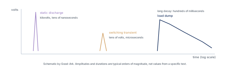
Load dump is the reason automotive electronics are specified and tested differently from consumer electronics. It is not a fault and it is not rare in the sense of being impossible: it is a normal consequence of how a charging system behaves when a heavy load is suddenly removed, and its duration is what makes it dangerous rather than its voltage alone.
Last updated:
What a load dump actually is
In a conventional vehicle the alternator charges the battery and supplies the electrical loads. Its output is regulated by controlling the current in a field winding, and that control loop has inertia: when the load changes, the field current takes time to adjust. If a large load is disconnected suddenly — a battery cable works loose, a high-current fuse blows, a jump-start connection is removed — the alternator is still producing current into a load that has vanished.
The regulator responds as fast as it can, but the field current decays over a period measured in hundreds of milliseconds rather than microseconds. For that entire time the alternator output voltage rises, and the energy has to go somewhere. The result is a voltage event that is slower and far more energetic than the microsecond-class transients that come from switching inductive loads, and it is described by its own test waveform in automotive standards.
Why the voltage spikes so high
The commonly quoted figure for an unclamped load dump in a 12 V system is around 87 volts, decaying over several hundred milliseconds. That number is a test definition rather than an observation: the exact amplitude and duration depend on the specification being applied, the alternator’s characteristics and whether the vehicle provides central clamping. What is consistent across specifications is the shape — a fast rise followed by a long decay.
The comparison with static discharge is the useful one. A static event delivers kilovolts in tens of nanoseconds, so it is a voltage problem. A load dump delivers a few tens of volts over hundreds of milliseconds, so it is an energy problem. A component that survives the first may be destroyed by the second, and vice versa, which is why automotive parts are specified against a set of different pulses rather than one number.
What happens to unprotected electronics
A component designed for a 12 V rail is typically rated for a maximum input somewhere between roughly 20 and 40 volts, and a module’s input filter is designed around that. A load dump clamped by central protection in the vehicle may present something in that range. An unclamped event does not, and the first thing in the path to exceed its rating fails.
The failure is usually not graceful. A semiconductor driven beyond its voltage rating can break down, and the resulting current can destroy the device and sometimes the board around it. In a module with several inputs, the failure can propagate through the shared supply. In a vehicle, a failed control module produces symptoms that look unrelated to the electrical event: a warning light, a function that no longer responds, a battery that drains.
| Event | Typical duration | What it stresses | What protects against it |
|---|---|---|---|
| Static discharge (handling) | Tens of nanoseconds | Gate oxides and thin structures | On-board ESD clamps, and handling discipline |
| Switching transient (inductive load) | Microseconds | Input clamps and driver outputs | Fast clamping diodes at the affected node |
| Load dump | Hundreds of milliseconds | Input stages and supply filters | Central vehicle clamping, plus module-level clamps sized for the residual |
| Reverse polarity | Until corrected | Everything with a defined polarity | Series protection and fuse coordination |
How cars protect themselves
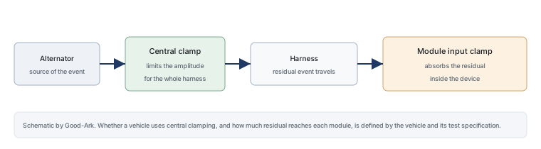
Two layers do the work. The first is central clamping: the vehicle may include a protective device at the alternator or in the distribution system whose job is to limit the load-dump amplitude before it reaches the harness. Where this exists, the event arriving at each module is much smaller than the unclamped figure, which is why the test specification for a module is defined in terms of a clamped waveform.
The second layer is local: every control module has its own input protection, sized for the residual waveform the specification defines and for the module’s own tolerance. This is why an automotive part cannot simply be replaced by an electrically similar commercial part — the commercial part was never specified against that waveform, even if its voltage rating appears adequate.
The role of a TVS diode
In module-level protection, a clamping diode absorbs the residual event by conducting above a threshold and holding the input within what the electronics can tolerate. Sized for energy rather than voltage alone, it converts what would be a destructive supply excursion into heat inside a component chosen to take it.
The specification detail that matters is the duration. A part chosen for microsecond transients will have a peak pulse rating that looks impressive and is measured over a far shorter window than a load dump. For a load dump, what counts is the energy the device can absorb over hundreds of milliseconds and how hot it gets doing so — which is why automotive parts are selected from families qualified for these events rather than from a general catalogue sorted by voltage. The general principle is explained in the article on transient voltage suppression, and the functional view of automotive parts is in the automotive portfolio article.
Why this matters more in EVs and hybrids
A common assumption is that electric vehicles face the same load dump, only worse. That is not quite right, and the difference is worth understanding because it changes what designers protect against. An electric vehicle has no alternator, so the classic mechanism — a field winding whose current cannot be reduced instantly — does not exist.
What an electric vehicle does have is a 12 V rail produced by a DC-DC converter from the high-voltage pack, plus the same inductive loads as any other car: motors, pumps, fans, relays and contactors. Those loads generate switching transients when they turn off, and the converter has to manage the rail during large load steps. So the transient environment is still demanding, but it is shaped differently, and the test specification applied to a module reflects that. Electrified vehicles also add high-voltage events that a conventional car never had, which is a different protection problem with its own requirements.
Four external sources are worth reading if you want the standards context. The machine that creates the event is described under alternators, and the protection device under transient voltage suppressors. The test waveforms that define a load dump come from the ISO automotive standards series and from the International Electrotechnical Commission; device-level measurement methods come from JEDEC; and broader sector reporting from the Semiconductor Industry Association. Standards and measurement background is published by NIST and IPC.
What drivers can observe
From the driver’s seat, a load dump is usually invisible when protection works. When it does not, the symptoms are indirect: a module that has stopped responding, a warning lamp that stays on, a battery that goes flat because a charging-related control module is drawing current, or a function such as a window or a light that no longer operates. Nothing about those symptoms points back to an electrical event that lasted less than a second.
For a technician, the useful habit is to suspect a transient event whenever a module has failed in a way that does not match normal wear — especially after a jump-start, a battery replacement or work on the charging system. That history is often the missing piece.
FAQ
What does “load dump” mean?
It describes the voltage event that follows the sudden loss of a large electrical load while a charging source is still delivering current. The source’s control loop cannot reduce its output instantly, so the voltage rises for as long as the excess current has nowhere to go — typically a few hundred milliseconds. The name comes from the fact that the load has been dumped; the event is a consequence of the source, not of the load.
What is load dump testing and what does it do?
It applies a defined voltage waveform to a module’s supply input to represent the event, and checks that the module continues to function or at least survives without damage. The point of testing rather than analysing is that the waveform has both amplitude and duration, and a module’s behaviour depends on both — a filter that shrugs off a short spike may be overwhelmed by the same amplitude sustained for hundreds of milliseconds. The specification defines the shape, so results from different test houses can be compared.
Can a fuse prevent a load dump?
No. A fuse protects against excessive current over a sustained period and operates far too slowly to shape a voltage event. Fuses matter in the same system, because a loose or blown connection is one of the ways a load is dumped in the first place, but the voltage that results has to be handled by clamping rather than by interrupting.
Is a load dump the same as a surge from lightning?
They share a family resemblance — both are voltage events with energy behind them — but they differ in origin, duration and the path they take. Lightning-induced surges arrive on external conductors and are typically faster and higher in voltage; a load dump is generated inside the vehicle’s own charging system and lasts far longer. A design that handles one has not automatically handled the other, which is why automotive specifications list several events separately.
Where should I start with automotive protection?
Start from the test waveform the module has to meet, then work back to the input filter and the clamping part. Starting from a component and asking whether it is good enough reverses the order and usually produces a design that passes on paper. The functional split of automotive device families is described in the automotive portfolio overview.
What to do next
The useful takeaway is that automotive protection is specified by event, not by voltage. If you are designing a module, find the waveform your customer requires before choosing anything, and check the energy a candidate part can absorb for that duration. The wider context for automotive-grade parts is in the article on what automotive grade actually means, and the component families are grouped in the product family learning centre.
Tell Good-Ark the input rail, the waveform your specification requires and the module’s tolerance, and we can point to the families qualified for that combination.
Email sales@goodark.com, or start with the application design centre.
This article is published by Good-Ark, a manufacturer of automotive-qualified discrete devices. The 87 V figure is the commonly quoted unclamped test level for a 12 V system and depends on the specification applied; no vehicle manufacturer or customer is referenced.
Continue through this engineering topic
For the complete selection, design, verification, and troubleshooting path, explore the Automotive Power Electronics Hub.
- Practical guide: The 12 V Automotive Rail: Transients It Sees, Components That Survive Them
- Practical guide: Load Dump De-Mystified: The 87 V Spike, Why It Happens, and How Components Survive
- Practical guide: MOSFETs and IGBTs in Electric Drives: Voltage Class, Frequency, and the Traction Trade
- Ask Good-Ark technical support about this application
Recommended
 Why Do Diodes Get Hot? Conduction and Switching Losses ExplainedInfoStandard, Fast Recovery, and Schottky Diodes: What’s the Difference?Info
 What Is a Fast Recovery Diode? Understanding “Fast Recovery”Info
 What Is a Diode? A Beginner’s Guide to How It WorksInfo
 Automotive Semiconductor Report 2026: Chips Per Car Keep RisingKnowledge