Why Do Diodes Get Hot? Forward Voltage, Current, and Heat for Beginners
Why do diodes get hot? One multiplication explains most of it: volts across the part times amps through it, with a worked example and the failure signs.
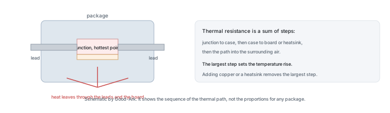
One multiplication explains most of it: the voltage across the diode multiplied by the current through it gives the power it turns into heat. Everything else — why some diodes run cooler, why a heatsink helps, why the same part survives in one product and fails in another — follows from that number and from how easily the heat can leave.
Warm or hot? A touch-based sanity check
Before measuring anything, a cautious touch tells you a lot. A device that is warm to the touch is usually dissipating a modest amount of power in a package that is doing its job. A device too hot to hold for more than a second is likely running beyond what its thermal path can carry, and a device that has discoloured the board around it has already been outside its limits.
Two cautions belong with that advice. Never touch a component in a live circuit — measure instead — and remember that your finger is not a thermometer. The useful version of the check is a comparison: the same diode in a similar circuit that used to be warm and is now hot is a signal, even if you cannot put a number on it.
The only formula you need today
Power dissipated in a forward-conducting diode equals forward voltage times forward current. In symbols, P equals V multiplied by I. For a silicon diode dropping roughly 0.7 volts at 1 amp, that is about 0.7 watts. For a Schottky diode dropping about 0.4 volts at the same current, it is about 0.4 watts.
Two refinements matter and neither needs algebra. First, forward voltage rises with current, so the relationship is not exactly linear — doubling the current raises the power by slightly more than double. Second, forward voltage falls as the junction heats, which slightly reduces the dissipation, and that reduction is one reason diodes do not always run away thermally the way a Schottky can when its leakage dominates.
A worked example with a 1 A load
The numbers below are invented and rounded to make the arithmetic visible. They are not a specification for any part, and real values differ substantially between packages and mounting methods.
| Step | Silicon rectifier | Schottky rectifier |
|---|---|---|
| Forward current | 1 A | 1 A |
| Forward voltage at that current | about 0.7 V | about 0.4 V |
| Power dissipated | about 0.7 W | about 0.4 W |
| Thermal resistance, junction to ambient, for a small axial package in still air | taken as 50 degrees per watt | taken as 50 degrees per watt |
| Calculated rise above ambient | about 35 degrees | about 20 degrees |
| Junction temperature at 25 degrees ambient | about 60 degrees | about 45 degrees |
| Junction temperature at 50 degrees ambient | about 85 degrees | about 70 degrees |
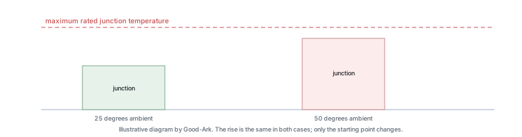
The last row is the one worth carrying away. At room temperature both parts look comfortable; at 50 degrees ambient, which is normal inside a sealed enclosure on a warm day, the silicon part is approaching its limit and the Schottky still has room. Nothing about the parts changed — only the environment.
The formula also explains why a diode that looks fine on a bench can fail in a product. Thermal resistance is measured with a specified mounting condition. A part that dissipates 0.7 watts on a small pad in still air may be dissipating the same power on the same pad inside a closed box, where the ambient is 30 degrees higher. The device did not degrade; the heat simply stopped leaving.
Why Schottky diodes run cooler
At low voltages, a Schottky diode drops less voltage than a silicon junction diode, so at the same current it dissipates less power. That is the whole advantage, and it is a substantial one in a low-voltage output stage where the diode may be carrying most of the load current.
The advantage has a limit that is easy to forget. Schottky diodes leak more in reverse, and that leakage rises steeply with temperature. In a circuit where the diode spends most of its time blocking, the reverse leakage can become a significant source of heat at high junction temperature, and because heat raises leakage, the two can reinforce each other. That is why a Schottky output can look excellent on a bench and fail in a warm enclosure, and it is the subject of our article on thermal runaway in Schottky diodes.
What heatsinking really does
A heatsink does not remove heat; it lowers the resistance to heat leaving. Adding copper area, a metal tab or an aluminium plate reduces the temperature rise for a given dissipation by improving the path from the device to the air. The result is a lower junction temperature at the same power, which extends life and reduces leakage.
Two practical points follow. The first is that the interface between the device and the heatsink matters as much as the heatsink itself: a mounting screw with no thermal interface material can leave a gap that dominates the path. The second is that the largest single step usually decides the outcome, so improving anything other than that step produces very little change. This is why a small amount of copper under a surface-mount diode often does more than a large heatsink bolted to a plastic package.
When heat means failure
Heat is a symptom rather than a fault in itself, and the useful question is whether the device is inside its ratings. In a repair context, three patterns point to heat as the mechanism rather than the symptom.
The first is discolouration: a browned board, a dulled lead or a cracked package surface indicates the device has been well beyond its design temperature. The second is a failed part with no other explanation — a diode that measures open or short in a circuit whose current and voltage are both within the expected range is often the end of a thermal story that started earlier. The third is a pattern of repeat failures in the same position, which usually means the thermal path was never adequate rather than that the replacement was faulty.
How to measure safely
Measuring temperature on a live board is a job for instruments, not fingers. The practical approaches are an infrared thermometer or a thermocouple held against the package, a thermal camera if one is available, or the device’s own forward voltage used as a temperature indicator before power is applied.
What you should not do is probe a live circuit with a metal object, short the leads of a device with a probe tip, or touch a component that has been running. If the circuit involves mains voltage or a battery pack, do not attempt a temperature measurement at all until it has been safely isolated; the measurement can wait, and the consequences of a slip cannot.
When to worry
The honest answer is that most warm diodes are fine and most cool ones are fine. Worry when the device is too hot to touch briefly, when the board around it has darkened, when a replacement in the same position fails again, or when the same part runs noticeably hotter than an identical one beside it. Each of those points to a thermal path that was never adequate or has degraded.
What you should not do is solve the problem by fitting a bigger diode without understanding the cause. A larger part spreads heat better and may solve a marginal case, but if the real problem is a mounting interface, a missing copper area or a shorted load drawing more current than the design expects, a bigger device simply takes longer to fail.
External references are useful here: the mechanism is described under thermal management in electronics, the device behaviour under diodes, and the surface-mount counterpart under surface-mount technology. Device measurement methods come from JEDEC, assembly and workmanship expectations from IPC, and sector-level context from the Semiconductor Industry Association. Device and assembly background is published by ISO, NIST and IEC.
FAQ
What are the signs that a diode is bad?
Electrically, a failed diode usually measures as a short or an open when tested out of circuit, and a badly degraded one measures asymmetrically compared with a known-good part. Physically, a cracked or discoloured body, a darkened board area or a dulled lead points to a thermal event. In a circuit, a shorted diode often shows as a dead rail or a fuse that blows immediately, while an open one shows as no output.
Do diodes go bad over time?
A diode has no wear-out mechanism in the way a battery does, but it can degrade through accumulated thermal cycling. Each heating and cooling cycle stresses the joints between the die, the package and the leads, and over thousands of cycles a weak point can open or become intermittent. In practice, most diodes that fail in service are pushed outside their ratings by something else in the circuit rather than simply ageing.
What would cause a diode to burn out?
Too much power dissipated in the junction, from too much current, too much voltage across it while conducting, or both. The dissipation may be legitimate but inadequately cooled, or it may be a symptom of a fault elsewhere that is drawing far more current than the design expects. Replacing the diode without finding which of those two applies is the reason repeat failures happen in the same position.
Is a warm diode normal?
Yes. Any diode carrying meaningful current is dissipating power, and that power leaves as heat, so warmth is the expected result rather than a fault. What matters is the junction temperature relative to the device’s rating, and that depends on the ambient conditions and the thermal path. The useful signals are a device that is too hot to touch briefly, one that has changed its behaviour over time, or one that runs hotter than its neighbour in the same circuit.
Does adding a heatsink always help?
It helps only if the path from the junction to the heatsink is better than the path that already existed. For a small axial part in free air, adding copper to the leads often does more than bolting on metal. For a surface-mount device, the copper area under the pad is usually the dominant term. Improving a step that is not the largest one in the chain produces very little change, which is why the diagnosis has to come before the remedy.
What to do next
Take the diode that runs hottest in a circuit you own and work out its dissipation: measure the forward voltage at the current it carries, multiply, and compare the result with what the package can shed in its mounting condition. That single calculation turns a vague concern into a number, and it is the same calculation a designer does before choosing a part. The physics behind it is in our article on how a diode works.
Give Good-Ark the current, the ambient conditions and the mounting, and we can point to the package and family that carry the dissipation with margin.
Email sales@goodark.com, or start from the product family learning centre.
This article is published by Good-Ark, a manufacturer of diodes and other discrete devices. The thermal figures in the worked example are invented round numbers used to show the arithmetic; real thermal resistance depends on package, copper area, airflow and mounting.
Continue reading
Browse the Rectifier Testing Failure and Reliability for related guides.
Recommended
 Why Does Your Phone Charger Get Warm?Knowledge
 Energy Efficiency Rules Worldwide: How Regulations Shape Component ChoicesKnowledge
 Wide-Bandgap Semiconductors: Adoption Report 2026Knowledge
 The GaN Charger Market: Why Your Next Adapter Is SmallerKnowledge
 Component Lead Times in 2026: What Is Actually Normal NowKnowledge
 China’s Power Semiconductor Industry: Where It Stands in 2026Knowledge