Why Do Diodes Get Hot? Conduction and Switching Losses Explained
A diode can work correctly and still run warm. Separate conduction and switching loss from heat removal to judge whether the rise is a problem.
Updated: October 27, 2026
Diodes get hot from conduction (I<sub>F</sub>×V<sub>F</sub>) and from switching/recovery energy—estimate both before blaming the heatsink alone.
Related reading: how to read a diode datasheet, datasheet terms explained, why not to trust every datasheet.
| Item | Verify | Typical trap |
|---|---|---|
| Conditions | Tj, IF, VR columns | Comparing numbers at different conditions |
| Curves vs tables | Which one your bias uses | Using only the cover headline |
| Absolute max | Never design at ABSMAX | No margin for spikes |
| Revision | Document date / PCN | Old PDF from a reseller |
How does forward conduction create heat?
Forward current flowing through the diode’s voltage drop produces conduction loss.
For an operating point with approximately constant current and forward voltage, a simple estimate is P ≈ VF × I. Power P is measured in watts, voltage VF in volts, and current I in amperes.
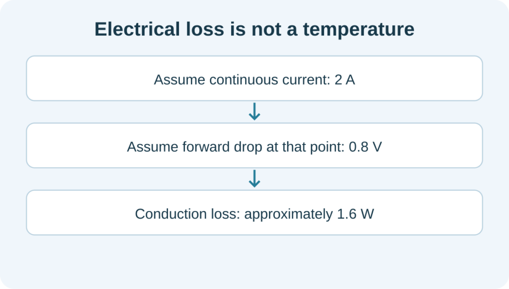
Take a hypothetical diode carrying 2 A continuously, with a forward drop approximated as 0.8 V at that operating point. Its conduction loss is approximately 0.8 V × 2 A = 1.6 W. That means about 1.6 joules per second becomes heat in the device. It does not mean a temperature rise of 1.6 degrees.
Both inputs are assumptions for this example, not guaranteed data for a product. If current varies, the forward voltage can vary too. Accurate loss calculations account for the waveform instead of assuming the peak current flows continuously. Vishay’s application note on diode power losses discusses the forward and reverse operating phases.

What changes when current flows in pulses?
Average loss must account for the whole cycle, including the intervals without forward conduction.
Suppose, as a separate simplified example, a diode carries a flat 2 A pulse for half of each cycle and no forward current for the other half. If its drop is approximated as 0.8 V throughout that pulse, the average conduction loss is 0.8 V × 2 A × 0.5 = 0.8 W.
The factor 0.5 is the duty cycle: the fraction of time spent in that assumed conducting state. Do not multiply by duty cycle again if a quantity already represents the full-cycle average under the same approximation.
Real waveforms may be triangular or curved, and forward voltage is not constant over an arbitrary current range. The example explains the time averaging; a more accurate estimate uses the actual waveform and an appropriate device model or measured voltage-current data.
Can switching transitions produce additional loss?
Yes. Voltage and current can overlap while a real device changes state.
In a simplified ideal switch, the conducting state has zero voltage and the blocking state has zero current. A real transition takes time. Energy can be dissipated during the interval when both voltage and current are present.
For a teaching example, assume one specified event dissipates 5 μJ in a particular device, occurs once per cycle, and repeats at 80 kHz. With that assumed event energy held constant, its average power contribution is 5 μJ × 80,000/s = 0.4 W. Two identical events per cycle would contribute 0.8 W. A plain-language introduction to the component itself is in What Is a Diode? The One-Way Valve Explained Simply.
Always state which device and event the energy belongs to. Diode recovery can also increase a transistor’s turn-on loss. Do not assign all recovery-related heating to the diode or add the same effect twice when combining loss estimates. ST’s analysis of diode turn-off losses describes why the circuit and actual voltage-current waveforms matter.
Can a blocking diode still generate heat?
Reverse leakage current under reverse voltage also produces power loss.
If reverse voltage and leakage are approximately steady, the loss during that blocking interval can be estimated as their product. To obtain a full-cycle average, also account for how long that state lasts.
For some silicon Schottky diodes, hot leakage is significant. Higher temperature can increase leakage, producing more heat, which can raise the temperature further. If the thermal system cannot handle this feedback, the operating point may become unstable.
ROHM’s discussion of Schottky thermal runaway explains this interaction. It is one reason why a lower forward drop does not automatically guarantee lower total loss over the entire operating cycle.
Why does the same power loss cause different temperatures?
Packages, mounting arrangements, boards, and airflow provide different thermal paths.
Heat must travel from the semiconductor junction through the package and its connections, then into the board, a heatsink, or the surrounding air. Thermal resistance describes how much temperature difference is associated with a given heat flow along a defined path. Its usual unit is °C/W.
Consider another independent teaching example. Assume an effective junction-to-ambient thermal resistance of 50°C/W for a particular mounting arrangement and a total average device loss of 0.6 W. Under a steady-state approximation, the temperature rise is 30°C. With ambient air at 35°C, estimated junction temperature is 65°C.
Those figures are assumptions, not a fixed property of a package type. Datasheet thermal resistance depends on its stated test conditions. Junction temperature means temperature inside the semiconductor, which is different from the package surface. Short pulses may also require transient thermal information rather than a steady-state calculation.

What should you check when a diode runs hot?
Identify the loss mechanism, then examine the thermal path.
In a continuous DC path, current and forward voltage are natural starting points. At a fast-switching position, also examine transitions and the behavior of the associated switch. If performance worsens markedly as the equipment becomes warmer, check leakage and available cooling.
Changing a diode can change heat generation. Improving copper area, thermal contact, or airflow can change the resulting temperature. These measures address different parts of the problem, so compare both before deciding what to change. The fast recovery diode guide provides further context for recovery-related loss and circuit stress.
Verification checklist
- Download from the official source when possible; record the revision.
- Recompute loss at your hot temperature, not only 25 °C.
- Treat marketplace PDFs without revision control as untrusted.
FAQ
Why do two PDFs for the same MPN disagree?
Revisions, region-specific docs, or altered reseller copies. Prefer the manufacturer repository.
What is the first datasheet section to read?
Absolute maximum ratings and the conditions footnotes—then the electrical table at your temperature.
Are part-number decoders reliable?
They are hints only. Family codes collide across vendors; the datasheet wins.
How does heating relate to datasheet limits?
See why diodes get hot and the thermal design guide.
Continue through this engineering topic
- How to choose the right power rectifier
- What is a diode explained simply
- 1N4001G rectifier diode
- 1N4004G rectifier diode
- Axial Rectifier Diodes Through Hole Assembly Replacement And
- Consumer Appliance Power Design Cost Sensitive Rectifier Choices
Topic hub: What is a diode — related selection guides and application notes in this cluster.
Explore the related topic guides
Continue with the related selection, design and verification guides: