What Is a Diode? The One-Way Valve of Electronics, Explained With Everyday Pictures
A diode conducts one way and blocks the other. See where you already use diodes and the three numbers that describe every one of them.
Updated: October 27, 2026
A diode is a two-terminal device that conducts easily in one direction and blocks in the other—electronics’ one-way valve—characterized mainly by VF, VRRM, and current limits.
Below is a practical definition, the ratings that matter, and where this part sits among related guides: How to choose the right power rectifier, 1N4001G rectifier diode, 1N4004G rectifier diode.
| Question | Short answer | Watch-out |
|---|---|---|
| Forward | Conducts above ~VF | VF rises with current |
| Reverse | Blocks until VRRM/breakdown | Leakage is never zero |
| Types | Si, Schottky, Zener, LED… | Not interchangeable by symbol alone |
| First checks | Polarity + ratings | Ignoring temperature |
The one-sentence answer
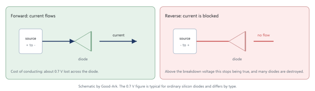
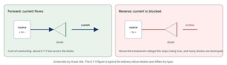
A diode is a two-terminal semiconductor device that allows current to flow from one terminal to the other but not in the reverse direction, which makes it the electronic equivalent of a one-way valve. Under normal operation it drops a small voltage while conducting — around 0.7 volts for an ordinary silicon diode — and blocks almost entirely when the voltage is reversed, up to a defined limit.
Two terminals, two directions, one number to remember. Everything else about diodes is about how well they do those two things, how fast they stop conducting, and how much energy they can survive while doing it.
A water-pipe analogy that actually works
Picture a pipe with a hinged flap inside. Water flowing one way pushes the flap open and passes; water trying to flow the other way presses the flap shut and stops. A diode behaves the same way for electric current, with two useful caveats that the analogy misses.
The first caveat is the pressure drop. The flap costs a little pressure even when it is wide open, and a diode costs a little voltage — that 0.7 volts — while conducting. The second is the failure mode. If you push hard enough in the blocked direction, the flap breaks and lets everything through; a diode does the same at a voltage called the breakdown voltage, and in many diodes that event is destructive. So the analogy is useful for the direction and misleading for the limits, which is exactly where beginners get caught. To see where diode heating comes from, read Why Do Diodes Get Hot? Conduction and Switching Losses Explained.
The diode symbol and what each part means
The standard symbol is a triangle pointing at a vertical bar. The triangle is the anode, the terminal current enters when the diode is conducting; the bar is the cathode, the terminal current leaves. The direction the triangle points is the direction conventional current flows, which is why the symbol is read as an arrow rather than as a shape.
The reason the symbol looks like a valve rather than a component is that it is a behaviour diagram, not a picture. Engineers need to see at a glance which way current may flow, and the triangle does that in a way a drawing of a plastic package never could. Once you have seen the symbol on a schematic and the band on a real part, the two are easy to connect — and that connection is the subject of our article on identifying the anode and cathode.
Forward and reverse: the two directions
Connect a diode so that its anode is toward the positive terminal and the diode conducts. Connect it the other way and it blocks. That is the whole behaviour in one sentence, and the two names for the conditions are forward bias and reverse bias.
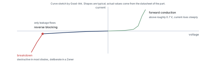
Three details matter in practice. Forward conduction is not free: a small voltage is lost across the diode, and that loss appears as heat. Reverse blocking is not perfect: a tiny leakage current flows, and it grows with temperature. And the blocking has a limit: exceed the reverse voltage rating and the diode either breaks down in a controlled way, as a Zener does deliberately, or is destroyed.
It is worth separating two meanings of the word that cause confusion later. A diode’s direction of easy flow is a property of the part, but which way it faces in a circuit is a design decision: the same component can be fitted to conduct during normal operation, as a rectifier does, or to conduct only during a fault, as a protection diode does. Both are the same device doing the same thing. The difference is the designer’s intent and where the current is expected to come from. Beginners who hold that distinction separately find protection circuits much easier to read.
Where you already use diodes
You are surrounded by them. A phone charger rectifies alternating current into direct current using diodes, and the bridge rectifier at its input is four of them in one package. Solar panels use bypass diodes so that a shaded cell does not overheat. A car’s electrical system uses them to protect control units from the transients that inductive loads create. A battery-powered device uses them to stop the battery discharging into the charger or the wrong way round.
The scale is worth pausing on. Rectifier diodes are among the highest-volume electronic components manufactured, because almost anything that plugs into a wall socket converts power at some point. That is why a device class this simple supports an entire industry.
What a diode is not
Clearing this up prevents most early confusion. A diode is not a resistor: its resistance depends on the direction and the current, not on a fixed value. It is not a switch you operate: it decides for itself based on the voltage across it. It is not a fuse: it does not disconnect a circuit, and a failed diode often fails short, which creates a fault rather than clearing one. And it is not a one-way gate for power only — the same component appears in signal paths, where it steers or blocks small currents rather than large ones.
For external background, three references are useful. The general behaviour is described under diodes, the ordinary rectifier circuit under rectifiers, and the light-emitting member of the family under light-emitting diodes. Device test methods come from JEDEC, board assembly expectations from IPC, and sector-level context from the Semiconductor Industry Association. Device and assembly background is published by ISO, NIST and IEC.
Three numbers that describe every diode
Every diode datasheet is a long document, and three numbers do most of the work for a beginner.
| Rating | What it means | Typical value | What happens if you exceed it |
|---|---|---|---|
| Forward voltage | The voltage lost across the diode while conducting | Around 0.7 V for ordinary silicon; lower for Schottky | Not exceeded as such — but higher current means more heat |
| Forward current | The current it can carry continuously, at a stated temperature | Depends entirely on the part | Overheating, then failure |
| Reverse voltage | The voltage it can block in the reverse direction | Depends entirely on the part | Breakdown, which is destructive in most diodes |
Those three are enough to reason about a simple circuit, and they map onto the three questions beginners ask: how much voltage does it cost me, how much current can it carry, and how much voltage can it hold off. Everything else on the datasheet refines those answers with conditions.
Bridging to the next topic
The next useful steps are practical rather than theoretical. Learning to identify which end is which prevents the most common beginner mistake, and learning what the printed codes mean lets you work with parts you already have. Both are covered in this cluster: start with anode and cathode identification, then move to how the junction actually works.
Field checklist
- Identify anode/cathode marking before power-up.
- Match VRRM and IF with margin.
- Move to Schottky/Zener/TVS pages when the job is specialized.
FAQ
How do I test a diode with a multimeter?
Diode mode shows a forward drop one way and open the other on a healthy Si diode—out of circuit when possible.
Is every black axial diode a 1N4007?
No—read markings and measure; many look similar.
Why care about temperature?
Both VF and leakage change with Tj; hot designs need re-checks.
Next reads?
How to read a diode datasheet.
Continue through this engineering topic
- How to choose the right power rectifier
- 1N4001G rectifier diode
- 1N4004G rectifier diode
- Why Do Diodes Get Hot Conduction And Switching
- Axial Rectifier Diodes Through Hole Assembly Replacement And
- Consumer Appliance Power Design Cost Sensitive Rectifier Choices
Topic hub: What is a diode — related selection guides and application notes in this cluster.