Good-Ark 10A05 Rectifier: Specifications, Polarity and Applications
The Good-Ark 10A05 rectifier is a standard silicon rectifier with a listed 10 A average-current rating and a 50 V repetitive peak…

The Good-Ark 10A05 rectifier is a standard silicon rectifier with a listed 10 A average-current rating and a 50 V repetitive peak reverse-voltage rating, in an R-6/P600 axial package. It passes useful forward current and resists reverse current. Those numbers identify the device class; they do not establish that it can carry 10 A on any board, withstand mains voltage or replace a high-frequency rectifier.
The decisive reference is Good-Ark’s 10A05–10A10 datasheet, Rev. B, released February 22, 2024. This guide separates what that document lists from application calculations and practical checks. In particular, it does not assign a reverse-recovery time that the reviewed sheet does not specify, and it does not turn a one-pulse surge rating into a continuous operating allowance.
Last updated:
The important 10A05 specifications and their conditions
The 10A05 is the lowest-voltage member of the reviewed family. Higher suffixes identify other reverse-voltage classes in that document. Confirm the manufacturer and full ordering code, because different manufacturers may publish different package, temperature or surge information for familiar base numbers.
| Parameter | Reviewed Good-Ark value | How to read it |
|---|---|---|
| Repetitive peak reverse voltage, VRRM | 50 V | A blocking limit, not the forward voltage drop |
| Average rectified forward current, IF(AV) | 10 A | Use the rating, derating and mounting conditions together |
| Forward drop, VF | 1.0 V at IF = 10 A | Listed test point; not a fixed drop at all currents |
| Forward surge, IFSM | 600 A | Specified 8.3 ms single half-sine pulse condition |
| Operating junction temperature | −55 to +135 °C | Distinct from the +150 °C storage limit |
| Package | R-6/P600 | Verify the actual outline and mounting |
The official Good-Ark Rev. B datasheet also notes a lead-temperature condition at 9.5 mm from the case. Read that note with the ratings and curves. Temperature, mounting and waveform are part of the specification, not optional details to add after a component runs too hot.
Which end is the cathode?
An axial rectifier’s cathode is normally indicated by a band. Conventional forward current goes from anode to cathode. The diode-symbol bar denotes the cathode too. Confirm the actual marking against the product documentation rather than using lead length or the orientation of printed text as a substitute for polarity identification.
For a simple positive half-wave rectifier, the anode faces the transformer source and the cathode faces the positive output path. A reversed installation changes which half-cycle can conduct or prevents the intended charging path. In a bridge, the four diode orientations work together, so understanding one band does not by itself identify all bridge terminals.
Board markings should be checked as well. A replacement that follows the old component’s orientation can preserve an earlier installation mistake. Read the circuit and the diode identity together. If the band is obscured or the device is damaged, investigate the part and connections before powering the circuit.
A 12 V transformer example—and what it does not prove
Consider a hypothetical isolated 12 V RMS sine-wave transformer secondary feeding a bridge. Its ideal peak voltage is 12 × √2, or about 17.0 V. The capacitor can charge toward that peak minus the two conducting junction drops, with the actual value depending on loading and the source. It should not be described as an automatically regulated 12 V DC supply.
The transformer’s no-load voltage, input variation, wiring impedance and charging pulses still matter. Check the reverse stress in the chosen topology and the surge produced when a discharged capacitor is first connected. A smaller capacitor does not automatically eliminate the problem, and a large pulse label does not demonstrate unlimited repeated charging capability.
Contrast that isolated low-voltage example with a 120 V RMS mains input: the ideal sine peak is about 170 V, already well above the 10A05’s 50 V rating. Direct 230 V RMS input is higher still. The 10A05 therefore cannot be approved as a direct mains bridge diode from its current rating. High-current capability cannot compensate for inadequate reverse-voltage capability.
Why the 10 A label does not guarantee cool operation
Forward conduction dissipates heat. As a first approximation, use the time-average of current multiplied by forward voltage; for a roughly constant current, P ≈ I × VF. Waveform and temperature dependence matter when refining the estimate. The listed VF test point is not a constant voltage drop for every operating state.
For a hypothetical 5 A operating point with a justified 0.9 V forward-drop estimate, the conduction loss would be 4.5 W. In a constant-current bridge path, two comparable junctions would contribute about 9 W in total. Those are illustrative calculations, not measured Good-Ark results or an approved loading recommendation. A capacitor-input waveform requires its own analysis.
Heat must leave through the package and leads into the installed surroundings. Typical thermal-resistance values in a document describe particular reference paths and conditions; they are not permission to ignore lead geometry, copper or enclosure temperature. Validate the hottest credible operating state. Keep the junction limit separate from the storage-temperature limit, because an unpowered storage allowance does not justify hotter powered operation.
What does the 600 A surge specification mean?
It describes the specified single-pulse test condition. The reviewed sheet lists an 8.3 ms half-sine surge, not a continuous 600 A current and not a general promise for every pulse shape. Duration, starting temperature and repetition affect the stress. A rectangular pulse, repeated capacitor recharge or a poorly limited fault is a different condition.
This is why startup evaluation belongs to the actual circuit. Identify the discharged capacitance, source impedance, switching conditions and credible repeated starts. Where needed, use suitable inrush control or choose a device with evidence that supports the required waveform. A pulse rating can be one part of that review, but it does not replace it.
The rating is also not a fuse-coordination result or evidence that downstream components remain protected. Leads, tracks, connections and other parts may have their own limits. Keep semiconductor survival and system protection as separate questions so a robust-looking diode number does not conceal a weaker part of the path.

Is the 10A05 a fast-recovery diode?
The reviewed family is titled standard rectifiers. Its feature list contains a fast-switching phrase, but the reviewed electrical tables do not provide a reverse-recovery time or charge that establishes high-frequency commutation performance. Do not resolve that inconsistency by inventing a number such as “above 500 ns,” or by treating a promotional bullet as an application guarantee.
If the circuit forces rapid reverse commutation, obtain device-specific switching evidence or select a suitable fast-recovery, Schottky or other rectifier supported for that role. A diode at a low-frequency input stage and a diode at a switched output stage have different requirements, even inside the same power supply. “Used in an SMPS” is too broad to define the job.
The fast-recovery diode guide explains the commutation questions. For the 10A05, the responsible conclusion is limited: its basic ratings identify a low-voltage standard rectifier candidate, while a high-frequency use needs evidence beyond the reviewed sheet.
How should a diode-mode test be interpreted?
A low-current meter test can expose a gross fault. With power removed, stored energy discharged and the device properly isolated as required, a normal silicon junction commonly shows a forward reading in one direction and an open indication in the other. The exact reading depends on meter conditions, device temperature and the junction.
A low reading both ways can indicate a short, but an in-circuit parallel path can give a similar result. An open indication both ways can indicate a failed junction, poor contact or another measurement limitation. If the reading changes, capacitors or surrounding components may be influencing the result. Resolve those conditions before condemning the diode.
A meter does not apply the rated reverse voltage or the intended operating current in ordinary diode mode. It cannot confirm hot leakage, surge endurance or high-frequency behavior. Use the equipment’s service procedure and the part-specific sourcing checks when replacing a failed device. Finding a diode fault does not establish why it failed or whether a surrounding circuit fault remains.
Replacement checks within and beyond the family
A higher-voltage family member may be worth evaluating when reverse capability is insufficient. In the reviewed sheet, 10A1, 10A2 and 10A10 correspond to 100 V, 200 V and 1000 V repetitive reverse classes. That does not make them automatically approved replacements: confirm the full device, package, characteristics and the application’s acceptance requirements.
Across manufacturers, compare the actual documents rather than merging specifications from different 10A05 listings. Package dimensions, surge conditions and maximum operating temperature can differ. A retailer’s summary is not a substitute for a matched datasheet. If the original failure involved heating or startup, changing only the voltage rating may leave the cause untouched.
Replacing a standard rectifier with a Schottky device can alter leakage and forward behavior; replacing it with another package can alter the heat path. The useful question is whether the new candidate meets the circuit conditions and assembly constraints. That approach is more reliable than searching for a diode whose ratings merely look larger.
Use the 10A05 data, not a generic rectifier label
This page owns the 10A05 specifications and replacement checks. For the conversion principle, use the power rectifier explanation; for the meaning and limits of meter readings, use the diode-mode test guide. Keep the exact part’s voltage, surge, package, and thermal conditions with every application decision.
Frequently asked questions
What does 10A05 mean in the Good-Ark rectifier family?
The reviewed Good-Ark family identifies 10A05 as a standard rectifier with a listed 10 A average rectified-current rating and 50 V repetitive peak reverse rating. Read the table and mounting conditions rather than decoding the name as a complete specification. Different manufacturers can use familiar base numbers with different supporting details. For purchasing or replacement, retain the manufacturer, full ordering code, package and applicable document revision alongside the family designation.
Can a 10A05 rectify household mains voltage?
The 50 V reverse rating is inadequate for direct rectification of ordinary 120 V or 230 V RMS mains inputs. An ideal 120 V RMS sine wave already peaks at about 170 V, before relevant transients or tolerance. A suitably isolated low-voltage transformer output is a different circuit and still needs voltage, current, surge and thermal review. Never use the 10 A label to justify a voltage class that cannot withstand the intended input.
Why does a 10A05 run hot below 10 A?
The rating is tied to specified conditions, while the installed device dissipates forward-conduction power through its real heat path. Lead length, board copper, ambient temperature, enclosure and the current waveform can change the result. Charging pulses also differ from a steady load. Estimate losses using the relevant forward behavior and verify the mounted temperature. A part operating below its headline average-current rating can still exceed its junction limit if cooling or waveform assumptions are wrong.
Is the 10A05 the same as a 10A10?
They are different voltage classes in the reviewed family: 10A05 is listed at 50 V repetitive reverse voltage and 10A10 at 1000 V. Sharing a family and nominal average-current rating does not establish identical behavior in every circuit. Check package, full ordering information and relevant characteristics before substituting. A higher reverse rating may solve a voltage constraint, but it does not independently prove acceptable surge, mounting, loss or switching performance.
Does a good multimeter result mean the diode is reusable?
It supports only the behavior observed at the meter’s test conditions. A device can pass a low-current forward check while failing at working reverse voltage, high temperature or load current. In-circuit components can also hide an open junction or mimic a short. Isolate and interpret the measurement using the service procedure, then consider the original failure conditions. Reuse decisions need the application-relevant evidence, particularly when the diode has experienced overheating or a surge.
Can I use the 10A05 as a solar panel bypass diode?
Do not approve it from the current rating alone. PV bypass use requires the protected substring voltage, sustained bypass current, hot reverse leakage and the actual junction-box heat path to be evaluated. The module’s validated construction and service requirements also apply. A standard rectifier’s familiar name does not establish installed PV qualification. Select a candidate supported for the exact role and conditions, rather than treating all power diodes with similar current labels as interchangeable.
Match the low-voltage role to the evidence
The 10A05’s useful starting point is its documented 50 V standard-rectifier class and R-6/P600 package. Confirm polarity, reverse stress, startup and installed temperature before approval. Keep the reviewed datasheet with the decision, and treat missing high-frequency information as a real limit on what can be concluded.
Continue through this engineering topic
For the complete selection, design, verification, and troubleshooting path, explore the Rectifier Selection and Ratings.
- Practical guide: How to Choose the Right Power Rectifier: Ratings and Losses
- Practical guide: What Is a Diode? The One-Way Valve of Electronics, Explained With Everyday Pictures
- Practical guide: Inside a Diode Factory: How Diodes Are Manufactured, Explained Without Jargon
- Ask Good-Ark technical support about this application
Recommended
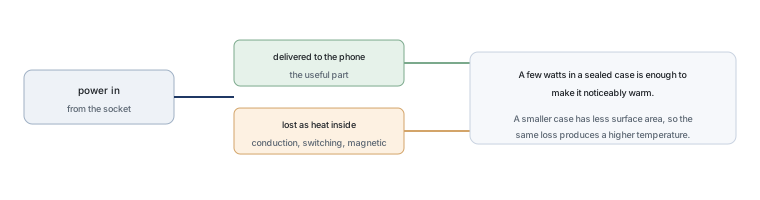 Why Does Your Phone Charger Get Warm?Knowledge
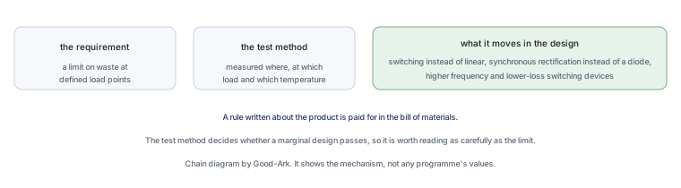 Energy Efficiency Rules Worldwide: How Regulations Shape Component ChoicesKnowledge
 Wide-Bandgap Semiconductors: Adoption Report 2026Knowledge
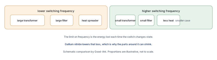 The GaN Charger Market: Why Your Next Adapter Is SmallerKnowledge
 Component Lead Times in 2026: What Is Actually Normal NowKnowledge
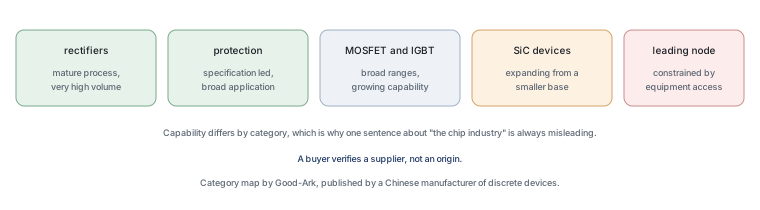 China’s Power Semiconductor Industry: Where It Stands in 2026Knowledge