1F5G Fast Recovery Rectifier: Specs, Polarity and Replacements
The Good-Ark 1F5G fast recovery rectifier is a single silicon diode rated at 1 A average forward current and 600 V repetitive…

The Good-Ark 1F5G fast recovery rectifier is a single silicon diode rated at 1 A average forward current and 600 V repetitive peak reverse voltage, in an R-1 axial package. Its maximum reverse recovery time is 250 ns under the manufacturer’s stated test conditions. These ratings help identify the part; they do not establish suitability for every switching circuit.
If you are replacing one on a board, match the manufacturer’s specification and package before applying power. The useful questions are how much reverse voltage it sees, what current waveform it carries, how hot it runs and how it commutates with the surrounding switches.
Last updated:
Where can you find the correct 1F5G data sheet?
Use the document for the actual manufacturer.
This guide uses Good-Ark’s 1F1G–1F7G data sheet, Rev. B. Find the 1F5G column and read the shared rows and footnotes.
A search result can contain a different supplier’s diode or even an unrelated product with a similar designation. Search snippets also sometimes call this part a bridge rectifier. Verify the original document instead of treating a search title as a component description.
The R-1 body has two axial leads. It is not a packaged four-terminal bridge. A full-wave bridge requires four appropriate diode junctions connected correctly, whether separate or inside an integrated bridge package.
Keep the full ordering code, document revision and package drawing with the replacement record. “1 A” and “600 V” are useful filters, but neither confirms lead spacing, temperature behavior or recovery performance.
What are the key Good-Ark 1F5G specifications?
Read each value with its conditions and parameter type.
The following values summarize the linked document. Maximum ratings, listed electrical values and typical characteristics serve different purposes.
| Parameter | Published value | Condition or distinction |
|---|---|---|
| Repetitive reverse voltage | 600 V | Blocking rating |
| Average rectified current | 1 A | Subject to mounting and thermal conditions |
| Forward surge current | 30 A | Single 8.3 ms half-sine on rated load |
| Forward drop | 1.30 V | Listed at 1 A |
| Reverse leakage | 5 μA / 100 μA | At rated reverse voltage, 25°C / 125°C junction |
| Reverse recovery time | 250 ns maximum | I_F = 0.5 A, I_R = 1.0 A, I_RR = 0.25 A |
| Junction capacitance | 12 pF typical | 4 V, 1 MHz |
| Junction temperature | −55°C to +150°C | Rated range, not a desired operating target |
The mounting footnote places the leads at ambient temperature 9.5 mm from the case. Do not transfer these values to a different manufacturer’s part or assume the board reproduces the data-sheet thermal setup.
How do you identify polarity and package fit?
Identify the cathode and check the mechanical drawing.
The cathode band shows the blocking and conducting orientation. Package body size, lead diameter and mounting geometry also matter when replacing an axial diode.
Trace the original circuit connection before removing the component. A photograph can help document orientation, but the board’s silkscreen and schematic should agree. A diode installed backward can block the intended current or create a fault path, depending on its role.
Compare the manufacturer’s R-1 outline with the available holes and body clearance. Another axial package may look similar while having different dimensions. Avoid forcing the leads into position with stress against the body; use the assembly instructions for the actual component.
Glass passivation describes the semiconductor junction treatment. It does not, by itself, mean a transparent glass outer package or establish environmental qualification.
What does 250 ns reverse recovery actually tell you?
It describes recovery under a specified switching test.
It is not a universal maximum switching frequency. The circuit’s current, temperature and rate of commutation affect the practical recovery waveform and loss.
A conducting PN diode stores charge. When forced into reverse bias, current briefly flows while that charge is removed. This can increase the paired switch’s turn-on stress and excite ringing in the commutation loop. Vishay’s rectifier fundamentals explains recovery as a parameter measured under stated conditions.
A shorter recovery time does not reveal all the information needed for selection. Recovery charge, peak current, softness and the surrounding parasitics can matter too. If the data sheet does not provide a needed dynamic characteristic, obtain supporting information or measure the representative circuit rather than inventing a value.
For the switching sequence and component roles, see how an SMPS works. The diode’s location in an auxiliary supply does not prove that its waveform is slow.
How should you calculate voltage and thermal margin?
Use the worst relevant waveform, not nominal voltage alone.
Check repetitive reverse peaks separately from non-repetitive events. Include tolerances, startup and ringing, then confirm the limits for the exact part.
As a topology illustration, a 230 V RMS sine wave peaks near 325 V. In an ideal half-wave circuit with a reservoir capacitor, a blocked diode can see about twice that peak, or 650 V. This exceeds a 600 V rating before adding margin. A bridge has a different reverse-voltage relationship, so the same nominal input cannot decide suitability for both arrangements.
For conduction loss, use the time average of v_F(t) × i_F(t). A hypothetical constant 0.5 A current and assumed 1.1 V forward drop gives 0.55 W. With an assumed applicable 75°C/W thermal path, the estimated steady-state rise is 41.25°C; actual switching and waveform losses must also be considered.
Toshiba’s junction-temperature explanation describes the thermal model. The example’s values are assumptions, not measured 1F5G performance or a board-level temperature guarantee.

Can another rectifier replace the 1F5G?
Only after electrical and mechanical comparison.
Compare the exact candidates under matching conditions. Equal blocking voltage does not establish equal recovery, forward loss, surge capability or footprint.
| Candidate | Why it might be considered | What remains to check |
|---|---|---|
| Another maker’s 1F5G | Similar base designation | Complete data sheet and package |
| Standard 600 V rectifier | Line-frequency rectification | Recovery if used in a switching path |
| Higher-voltage family member | More reverse-voltage capability | Its own recovery specification and losses |
| Ultrafast or Schottky part | Different dynamic behavior | Leakage, surge, forward loss and fit |
Even members of one family can have different recovery groups. Read the selected column rather than carrying one timing number across the series. For comparison with a standard rectifier, our 1N4002G guide explains the same rating discipline, although that part has a different voltage class.
Investigate why the original failed. A shorted load or uncontrolled overshoot can destroy a technically acceptable replacement as well.
Keep the 1F5G replacement decision at the device level
Use the cited 1F5G datasheet for package, polarity, recovery test conditions, and thermal limits. A replacement must meet the circuit requirements under comparable tests. The recovery and loss guide explains the shared physics without repeating it here.
FAQ
Can the 30 A surge rating be used as a repeated-current rating?
No. It is tied to a specific short surge waveform. Repeated pulses require their own current, thermal and reliability assessment; the surge label does not allow 30 A continuous operation.
Does a multimeter verify fast recovery?
No. Diode mode can check basic forward and reverse conduction with the power disconnected. It does not verify recovery time, rated blocking voltage or performance at temperature and load.
Is every part called 1F5G identical?
Do not assume that. Identify the supplier and full order code, then compare its electrical conditions, package drawing and lifecycle information. Similar naming is not a qualification record.
What should you record before installing one?
Record the manufacturer, revision, orientation and package, plus the voltage waveform, current demand and thermal assumptions that support the choice. Validate the representative circuit before treating a replacement as production-ready.
Continue through this engineering topic
For the complete selection, design, verification, and troubleshooting path, explore the Rectifier Selection and Ratings.
Recommended
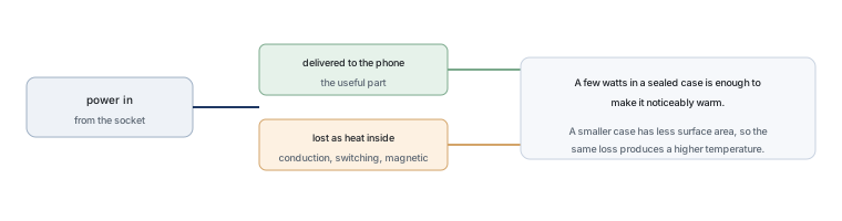 Why Does Your Phone Charger Get Warm?Knowledge
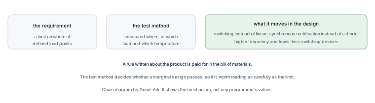 Energy Efficiency Rules Worldwide: How Regulations Shape Component ChoicesKnowledge
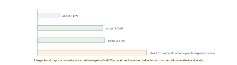 Wide-Bandgap Semiconductors: Adoption Report 2026Knowledge
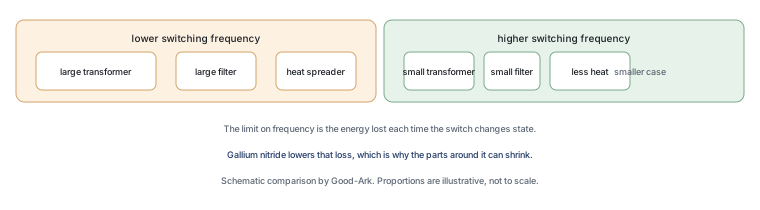 The GaN Charger Market: Why Your Next Adapter Is SmallerKnowledge
 Component Lead Times in 2026: What Is Actually Normal NowKnowledge
 China’s Power Semiconductor Industry: Where It Stands in 2026Knowledge