Clamping Voltage Explained: The Datasheet Number That Decides Protection
Clamping voltage explained: three voltage numbers appear on a protection datasheet and only one protects anything, with a worked 12 V example.
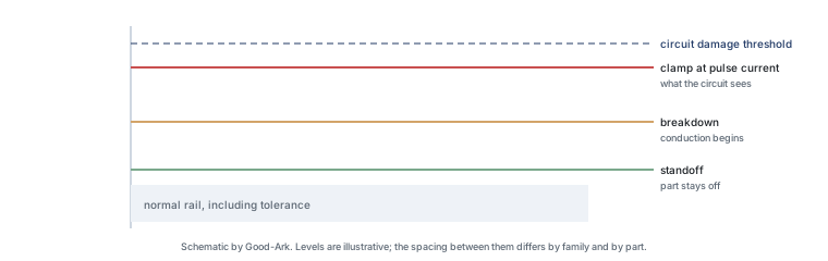
Three voltages are printed next to each other on a protection datasheet, they are all measured in volts, and only one of them tells you whether your circuit survives. Reading them in the wrong order is the single most common reason a correctly specified part fails to protect anything.
Last updated:
Three voltages on one line
The three numbers describe different moments in the life of the same component. The standoff voltage is the highest continuous voltage the part can tolerate without conducting; it belongs to normal operation. The breakdown voltage is where conduction begins, measured over a range and at a specified test current. The clamping voltage is what appears across the part while it is conducting a defined pulse current, and it belongs to the emergency.
The analogy that keeps them straight is a flood defence system. The standoff voltage is the height of the embankment during normal river levels. The breakdown voltage is where water first starts to spill over. The clamping voltage is how high the water still rises behind the barrier once the spillway is open — and that last number is the one that decides whether the town behind the wall is flooded.
Standoff: the everyday number
Standoff is the number you check first, because it describes the part’s behaviour 99.99 per cent of the time. It must sit above the highest voltage your rail reaches in normal operation, including supply tolerance, temperature effects and any legitimate transient that is not the event you are defending against. A device with a standoff below your rail will conduct continuously, leak, heat up and eventually fail without any surge being involved.
The margin here is a trade. A higher standoff keeps the part safely off but pushes the clamp up, because the two move together. A lower standoff gives a better clamp but leaves less room above the rail. Choosing that margin is the central design decision, and it is why the answer to “what is a good clamping voltage” always begins with a question about the rail.
Breakdown: where it starts to conduct
Breakdown voltage is where the device begins to conduct in reverse, and it is specified as a range rather than a single value because it varies between units and with temperature. This is the number beginners most often mistake for the protection level, and the mistake is understandable: it is the first voltage in the list that sounds like a limit.
It is not a limit, it is a doorway. At the breakdown voltage the device is only just starting to conduct, which means it is not yet diverting significant current and therefore not yet holding the voltage down. The part becomes useful as a clamp somewhere above this point, once the current has risen far enough for the device to present a low impedance.
Clamping: what your chip actually sees
The clamping voltage is measured while the part is conducting a specified pulse current, and it is the highest voltage your protected node will experience during the event. If the circuit behind that node can tolerate more than the clamp, the protection works. If it cannot, the protection works and the circuit fails anyway, which is a genuinely confusing outcome that the worked example below illustrates.
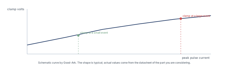
Because the clamping voltage is defined at a specific current, it is not a constant. Push more current through the device and the clamp rises; push less and it falls. A datasheet that lists a clamping voltage without a test current has given you half of a specification, and comparisons built on that half are not comparisons.
Why the clamp is not a wall
A protection device does not hold the voltage at a fixed ceiling regardless of what arrives. It offers a resistance that falls as the current rises, so the relationship between current and voltage is a curve. At low pulse currents the curve is steep and the clamp is close to the breakdown value; at high currents the curve flattens but the voltage keeps climbing.
That shape has two practical consequences. First, the clamp you quote must always be tied to a current, because the same part has many clamping voltages. Second, the part must be sized for the current the event will actually push through it, which depends on the source impedance of the event and on the impedance of the path the current takes to your return. Change the layout or the cable and you change the current, and therefore the voltage your circuit sees.
A 12 V rail worked example
The numbers below are invented for the arithmetic. They are not a datasheet for any part, and they are not a recommendation. The purpose is to show the order of the checks.
| Step | Value used | What it checks |
|---|---|---|
| Normal rail, including tolerance | 13.8 V | What the supply actually reaches in normal operation |
| Candidate standoff voltage | 15 V | Above the rail with margin, so the part stays off |
| Candidate breakdown voltage | 16.7 V typical | Where conduction begins; not the protection level |
| Candidate clamping voltage at 10 A | 24.4 V | What the protected node sees during the event |
| Maximum input of the circuit behind it | 20 V | The number that decides whether this works |
Read the last two rows together and the answer is uncomfortable: the clamp is 24.4 V and the circuit tolerates 20 V, so this part protects a circuit that was going to be damaged anyway. Every number is self-consistent, the part is genuine, the arithmetic is right, and the design fails. The only way to catch it is to compare the clamp against the circuit’s limit rather than against the rail voltage.
The fix is not to find a lower standoff part, because that would leave no margin above 13.8 V. It is to change one of the other numbers: accept a circuit with a higher tolerance, add a second protection stage with a lower clamping level, limit the current the event can deliver so the clamp sits lower on the curve, or reduce the energy reaching this node. Protection design is a negotiation between four numbers, and the rail voltage is only one of them.
Reading the graph quickly
Most protection datasheets include a curve of clamping voltage against peak pulse current, and it answers in one glance what the table cannot. Read three points: the voltage at a current typical of your event, the voltage at the maximum current you expect, and the current at which the curve starts to flatten. The third point tells you where you are getting good value from the part and where you are simply heating it.
Two other curves are worth a look. Leakage against temperature tells you whether the part will behave in a hot enclosure, and capacitance against voltage tells you whether it will disturb a signal. Neither appears in the headline table, and both decide whether the part works in the application rather than on the bench.
Two external references are worth reading before you settle on a part. The two device behaviours are described in the entries on transient voltage suppressors and Zener diodes, which share a mechanism and differ in specification. For the test methods that make one datasheet comparable with another, the source is JEDEC; for pulse definitions, the International Electrotechnical Commission; for assembly expectations, IPC; and for sector context, the Semiconductor Industry Association. Standards and measurement background is published by NIST and ISO.
Beginner FAQ
What is a good clamping voltage?
There is no absolute answer; a good clamp is one below the maximum voltage your protected circuit can tolerate, at the pulse current your event will actually produce, while the standoff voltage remains above your rail with margin. Those three conditions often cannot all be met by one part, which is why two-stage protection exists. A number quoted without a test current and without reference to the circuit behind it is not yet a good or a bad value.
How does the voltage-clamp work?
The device begins to conduct when the voltage across it crosses the breakdown point, and as the current through it rises its resistance falls. That combination holds the voltage close to a level that rises slowly with current rather than climbing as steeply as it would without the part. It is a dynamic balance rather than a switch, which is why the clamp is specified at a current.
What is the difference between clamping voltage and breakdown voltage?
Breakdown is where the device begins to conduct and is specified at a low test current. Clamping is what the device holds while conducting a much larger pulse current, and it is always higher than the breakdown value. Confusing the two makes a part look far better than it is, because the circuit sees the clamp, not the breakdown.
Is the voltage-clamp method still used today?
If the question is about shunt clamping with a semiconductor device, yes — it is the standard approach for protecting low-voltage rails and interfaces, and it has grown more important as circuits have become faster and less tolerant. If the question is about an older circuit-analysis technique that shares the name, that is a different subject. In protection work, the clamp is current technology rather than legacy.
Why does the clamp move when I change the layout?
Because the current through the device depends on the impedance of the whole path, not on the device alone. A longer or narrower trace raises the impedance, so less current flows through the clamp and more voltage appears across the trace before the part responds. The device has not changed; the circuit around it has.
What to do next
Write the four numbers down for the node you are protecting — rail with tolerance, standoff, the clamp at your expected pulse current, and the circuit’s maximum input — and check them in that order. If the fourth is smaller than the third, nothing else about the part matters. The rest of the selection method is in the TVS selection guide, and the families are grouped in the product family learning centre.
Send Good-Ark the rail voltage, the expected event current and the maximum input your circuit accepts, and we can tell you whether a candidate clamp fits or where the gap is.
Email sales@goodark.com, or start from the low-clamping-voltage example.
This article is published by Good-Ark, a manufacturer of protection devices. The numbers in the worked example are invented to demonstrate the arithmetic and are not a specification for any product.
Continue through this engineering topic
For the complete selection, design, verification, and troubleshooting path, explore the TVS ESD and Surge Protection Hub.
- Practical guide: How Does a Surge Protector Work? (And When It Quietly Stops Working)
- Practical guide: Lightning, Surges and Home Electronics: Where Protection Actually Sits
- Practical guide: ESD Protection for Beginners: Why a Tiny Diode Saves Your Phone
- Ask Good-Ark technical support about this application
Recommended
 Why Does Your Phone Charger Get Warm?Knowledge
 Energy Efficiency Rules Worldwide: How Regulations Shape Component ChoicesKnowledge
 Wide-Bandgap Semiconductors: Adoption Report 2026Knowledge
 The GaN Charger Market: Why Your Next Adapter Is SmallerKnowledge
 Component Lead Times in 2026: What Is Actually Normal NowKnowledge
 China’s Power Semiconductor Industry: Where It Stands in 2026Knowledge