From 12 V to 800 V: A Simple Map of Car Electrical Systems
Car electrical system voltages: a car runs on several at once. Why each layer exists, how they connect, and what the numbers mean at the battery terminals.

A car does not have “a” voltage. It has at least three, and in an electrified vehicle four, because different jobs are served best by different potentials. Treating them as one system is the source of a great deal of confusion, both for people diagnosing faults and for people designing components.
Why a car has several voltages
Voltage is a design parameter, and each layer of a vehicle chooses it to suit a different constraint. A low voltage is convenient for electronics and safe to work around. A higher voltage delivers the same power with less current, which means thinner cables and less loss, and it is what makes traction and fast charging practical. Each layer therefore sits at the level where its own trade is best.
The analogy that fits is a building with a mains supply, a low-voltage lighting circuit and a battery-backed alarm system. They coexist, they connect at defined interfaces, and each exists because the others are the wrong shape for its job. In a car those interfaces are converters rather than transformers, but the principle is the same.
12 V: the classic
The 12 volt system is the one every car has, and in most vehicles it still powers everything except traction: lighting, controls, sensors, comfort systems and the computers, which are also the parts that decide whether the car wakes up at all. In a conventional vehicle an alternator maintains it; in an electrified one a DC-to-DC converter does the same job from the high-voltage pack.
The numbers on a 12 volt battery are worth knowing because they are the most commonly misread measurements in motoring. A lead-acid battery at rest and fully charged sits somewhere around 12.6 to 12.8 volts. Around 12.4 to 12.5 volts it is partly discharged rather than faulty. With the engine running, a charging system typically holds the system at roughly 13.5 to 14.8 volts, and a reading in that band with the engine running is normal rather than a sign of overcharging.
| Condition | Typical reading | What it suggests |
|---|---|---|
| At rest, fully charged | Around 12.6 to 12.8 V | Healthy and charged |
| At rest, partly discharged | Around 12.2 to 12.5 V | Needs charging, or is being drained by something |
| At rest, substantially discharged | Below about 12.2 V | Charging is required before diagnosis is meaningful |
| Engine running, charging normally | Roughly 13.5 to 14.8 V | The charging system is working |
| During cranking | Drops substantially, then recovers | A large drop suggests a weak battery or a poor connection |
Two caveats belong with that table. Absorbed glass mat and enhanced flooded batteries used in vehicles with start-stop systems have slightly different behaviour, and a 12 volt lithium battery rests at a higher voltage entirely, so the bands above do not apply to it. And a resting voltage measured immediately after charging or after the engine has been running is not a resting voltage, because the surface charge has not dissipated yet.
48 V: the mild-hybrid answer
The 48 volt layer exists because 12 volts is not enough for the loads modern cars have added without making the cables unmanageable. A mild-hybrid system uses it for an electric boost function, for regenerative braking and for powering loads that would otherwise demand thick 12 volt cables.
It is described as mild because it does not drive the wheels alone; it assists. The engineering reason this layer appears is the same arithmetic that motivates higher traction voltages: at 48 volts, four times the power flows through the same conductor for the same current, so the wiring for a given function becomes lighter. The architecture usually keeps the 12 volt system alongside it, with a converter between them so that existing components continue to work.
400 V and 800 V: traction power
The traction layer sits in the hundreds of volts because that is where the trade between cable mass and insulation becomes favourable for the power involved. A nominally 400 volt pack has become the common starting point, and nominally 800 volt architectures have grown because they allow the same charging power through the same connector current.
The difference between them is not a doubling of performance. It is that for the same power, the current is halved, so conductor losses fall to a quarter and cables can be thinner. What it costs is more demanding insulation, larger clearances and semiconductors that can block the higher voltage while still switching efficiently, which is the reason wide-bandgap devices appear in these designs.
How the layers connect
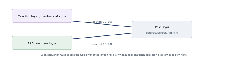
The layers connect through converters rather than through direct wiring, and that is what makes them coexist. In a mild hybrid, a converter moves energy between the 48 volt bus and the 12 volt one. In a battery electric vehicle, a DC-to-DC converter supplies the whole 12 volt system from the traction pack. In both cases the converter is the component that has to handle the full power of the lower-voltage system, which makes it a significant thermal design problem in its own right.
Isolation matters at these interfaces too. The traction layer is separated from the chassis and from the low-voltage systems by design, so that a fault in one cannot energise the other. That is why the converters are designed with isolation rather than as simple step-down circuits, and why the contactors that disconnect the pack in a fault are part of the same system.
What changes for each layer
The higher the layer, the more the design is governed by safety and insulation rather than by performance. At 12 volts, the dominant considerations are cost, size and quiescent current, because the voltage itself is not dangerous. At 48 volts, insulation and protection begin to matter more, and arc suppression becomes relevant when circuits are interrupted. At traction voltages, insulation, clearance, isolation monitoring and fault disconnection dominate the design, and the semiconductor devices have to block hundreds of volts while switching efficiently.
That progression explains why the same function appears in different forms at different layers. A switch that isolates a 12 volt load is a small part on a board; a switch that isolates a traction circuit is a contactor with its own control and diagnostic logic.
Where protection goes
Protection follows the boundaries, and higher voltages make it more consequential. At 12 volts, protection devices sit at connectors and inputs to absorb transients that the harness collects. At 48 volts the same idea applies with different device ratings. At traction voltages, protection overlaps with safety systems: isolation monitoring, insulation coordination, and disconnection under fault become part of the protection story rather than a separate topic.
One theme is constant across the layers. Protection belongs where the threat enters, physically close to the connector, with a short and well-defined return path. A device that is correctly rated and badly placed does not protect anything, and that is as true at 12 volts as it is at 800.
Three internal references connect this layer map to the rest of the material. The architecture of an electrified vehicle is described in our article on the power electronics inside an electric car, the reason high-voltage designs use wide-bandgap devices in why 800 V vehicles need silicon carbide, and the discharge path that a low-voltage system needs in load dump explained.
One-page map
The 12 volt layer is the universal one and is where most of the component count sits. The 48 volt layer exists to carry auxiliary power without heavy cables. The traction layer exists because high power at low voltage would need conductors a vehicle cannot carry. And the converters between them are what allow all three to coexist in one machine.
Our own articles cover automotive electronics, mild hybrid systems, and lead-acid batteries. Charging and connector standards come from the International Electrotechnical Commission, automotive safety and testing expectations from the ISO automotive standards series, and sector-level context from the Semiconductor Industry Association. Qualification and standards background is published by the Automotive Electronics Council, JEDEC and NIST.
FAQ
Is 14.8 volts too high for an alternator?
It is at the top of the normal range rather than outside it. Charging systems typically hold the supply somewhere between about 13.5 and 14.8 volts, and the exact value depends on temperature, battery type and the vehicle’s charging strategy. Many modern systems deliberately charge at different voltages depending on battery state, so a reading at the upper end is not by itself evidence of a fault. What would be abnormal is a reading above the manufacturer’s specification, or one that stays high with the battery clearly overcharged.
What voltage indicates a dead battery?
A lead-acid battery at rest below roughly 12 volts is substantially discharged, and one below about 11.8 volts is usually beyond the point where it can start a car reliably. The more useful measurement is taken under load: a battery whose voltage collapses far during cranking is failing even if its resting voltage looks acceptable. Because a resting measurement needs the surface charge to dissipate first, a reading taken immediately after charging or after the engine stops is not a resting reading.
Is 12.5 volts bad for a car?
At rest it suggests a battery that is partly discharged rather than faulty, since a fully charged lead-acid battery sits a little higher. With the engine running, 12.5 volts would be low and would suggest the charging system is not supplying properly. Which interpretation applies therefore depends entirely on whether the engine is running, and that is the detail most often left out when people compare readings online.
At what voltage will a car not start?
There is no universal threshold, because starting depends on temperature, engine size, battery condition and the current the starter draws. What is more useful is the behaviour under load: a battery that falls below roughly 9.6 volts while cranking is generally considered unable to deliver adequate starting current, and a slow crank with a large voltage drop points to a weak battery or a poor connection rather than to a marginal resting voltage.
Do electric cars have a 12 volt layer at all?
Most do, because the components that exist in every car — lighting, controls, sensors, the computers that decide whether the vehicle wakes — are built for a low-voltage supply. In an electric vehicle that layer is maintained by a DC-to-DC converter from the traction pack rather than by an alternator, which is why a failing low-voltage battery can produce symptoms that appear to come from the high-voltage system.
What to do next
If you are measuring a 12 volt system, note three things before drawing a conclusion: whether the engine is running, what the battery chemistry is, and how long ago the battery was charged. Those three details turn a number into a diagnosis. If you are designing for one of the higher layers, the voltage class is the first parameter because it determines the device family, the insulation requirements and the protection approach. The device side of the traction layer is covered in our article on why high-voltage vehicles use silicon carbide.
Tell Good-Ark which layer you are designing for, the transient environment and the thermal budget, and we can point to the device families and the qualification that fits.
Email sales@goodark.com, or start from the automotive portfolio page.
This article is published by Good-Ark, a manufacturer of discrete devices used in vehicle power electronics. Voltage bands are commonly used reference ranges for lead-acid systems and vary with temperature, load and battery chemistry; always consult the vehicle manufacturer’s specification for a specific vehicle.
Recommended
 Why Do Diodes Get Hot? Conduction and Switching Losses ExplainedInfoStandard, Fast Recovery, and Schottky Diodes: What’s the Difference?Info
 What Is a Fast Recovery Diode? Understanding “Fast Recovery”Info
 What Is a Diode? A Beginner’s Guide to How It WorksInfo
 Automotive Semiconductor Report 2026: Chips Per Car Keep RisingKnowledge