What Is a MOSFET? The Tiny Electronic Switch Explained Simply
A MOSFET is a switch you operate with voltage instead of a finger. What that means in a real circuit, where these parts hide in your home, and why they get hot.
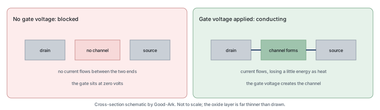
A MOSFET is a switch that is operated by a voltage rather than by a finger, and the reason it matters is the ratio involved: a signal you can barely measure can control a current large enough to burn you. Nearly every modern device that moves power or drives a motor contains several of them.
Last updated:
The one-sentence definition
A metal-oxide-semiconductor field-effect transistor is a three-terminal device in which a voltage applied to one terminal — the gate — creates an electric field that opens a conducting path between the other two, the drain and the source. The gate is insulated from that path by an extremely thin layer of oxide, which is why it draws almost no steady current.
Two words in that sentence do all the work. “Insulated” means the control side is electrically separate from the switched side, so a low-power circuit can command a high-power one. “Field” means the switching is done by an electric field rather than by a current flowing into the control terminal, which is what makes the control signal so small.
How a voltage opens a gate
Inside the device, the region between drain and source is deliberately made a poor conductor. Applying a voltage to the gate attracts charge carriers into that region and inverts its behaviour, creating a channel through which current can flow. Remove the gate voltage and the channel disappears, so conduction stops.
The analogy that works is a sluice gate in a channel, held closed by default and opened by a lever that requires almost no force to move. Two consequences follow from that picture and both matter practically. The lever has to be moved to a defined position to open the gate fully, which is why the gate voltage has to be high enough for the part. And the channel has some resistance even when fully open, which is why the device gets warm when current flows.
N-channel and P-channel, simply
There are two polarities of MOSFET, and the difference is which way round they sit in a circuit. An n-channel device conducts when its gate is driven above its source, and it is normally used as a low-side switch, meaning it connects the load to the negative supply. A p-channel device conducts when its gate is pulled below its source and is normally used as a high-side switch, connecting the load to the positive supply.
N-channel devices are far more common because they are cheaper and better for the same die area. The reason amateurs still meet p-channel parts is convenience: a high-side switch using an n-channel device needs a gate voltage above the supply, which requires extra circuitry, whereas a p-channel part can be driven from the supply directly. Our article on n-channel and p-channel devices covers the wiring conventions in detail.
Where MOSFETs live in your home
You will not see one, but several are within arm’s reach. In a phone charger a MOSFET chops the input current tens of thousands of times a second. In a laptop the processor’s power supply uses many of them. In an LED bulb the driver uses one or two. In a washing machine they drive the motor, in an e-bike controller they drive the wheel, and in a car they appear in window controllers, fan drivers, lighting modules and the traction inverter.
The pattern is consistent: anywhere a small decision has to control a large current, quickly and repeatedly. That covers motor drives, power conversion, battery management and load switching, which between them describe most of the electrical world.
Why they replaced mechanical switches
A relay or a mechanical switch works perfectly well for many applications, and both are still used. The reason MOSFETs displaced them in most electronics is a combination of four properties: nothing moves, so there is no contact wear; the control terminal consumes almost no power; switching can happen thousands of times per second; and the part fits on a board rather than in a socket.
The trade is that a MOSFET is more easily destroyed. Its gate oxide can be punctured by overvoltage, its channel can be cooked by excessive current, and it has no natural isolation between the control side and the switched side — which a relay provides for free. Choosing between them is the subject of our article on MOSFETs versus relays.
| Property | MOSFET | Mechanical switch or relay |
|---|---|---|
| Moving parts | None | Contacts and, in a relay, a coil and armature |
| Switching speed | Thousands of times per second and beyond | A few times per second at most |
| Control power | Almost none once the gate is charged | Continuous coil current for a relay |
| Isolation | None between control and load | Full electrical isolation at the contacts |
| Failure mode | Often short circuit, which is hazardous | Often open, which is safer |
| Size | Millimetres, board-mounted | Centimetres, often socketed |
| An audible click | None | Yes, which can be useful feedback |
One structural feature is worth knowing because it causes surprises. A power MOSFET contains a body diode between source and drain as a consequence of how it is built, which conducts in the reverse direction whether or not you wanted it to. In a simple load switch that is usually harmless or even useful, since it gives the load a path when the device is off. In a bridge or a bidirectional circuit it becomes a design constraint, because the device cannot block in both directions however firmly the gate is held closed.
Three numbers on a datasheet
The blocking voltage sets the class and must exceed the highest voltage the device will see, including transients. The on-resistance determines how much heat is produced while conducting, and it rises with temperature. The gate threshold and gate charge determine how the device has to be driven, and getting those wrong is the most common reason a design appears to work while running far hotter than expected.
The one that catches beginners is the gate requirement. Devices specified for logic-level drive reach their rated on-resistance at a gate voltage a microcontroller pin can supply; others need more, and driving one of those from a logic pin leaves it partially on, which multiplies the heat without changing the behaviour enough to look wrong.
What makes one get hot
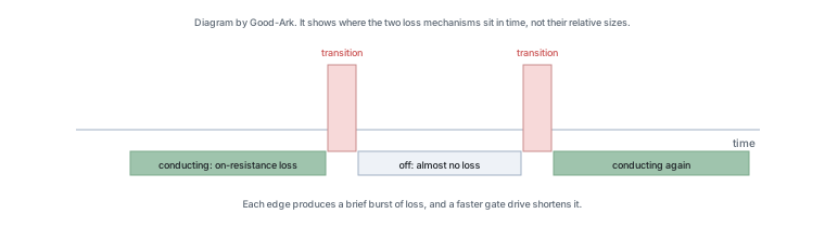
Two mechanisms, and they are worth separating. While conducting, the device behaves like a small resistance, so heat rises with the square of the current — double the current, four times the loss. While switching, the device passes through states where both voltage and current are present at the same time, so each transition produces a short burst of loss. A part that switches often can therefore be hot even when its on-resistance looks excellent.
That second mechanism explains why gate drive quality matters as much as the part number. A slow gate drive keeps the device in the lossy intermediate state for longer, every cycle, which turns a good device into a hot one. The practical consequences are covered in our article on gate drive design.
Next steps for beginners
Three things are worth learning in order: how to read the three numbers above, how to drive the gate properly for the part you are using, and how to estimate the junction temperature from the power dissipated and the thermal resistance. Those three cover the majority of beginner mistakes, and none of them requires mathematics beyond multiplication.
Background written for beginners covers MOSFET and field-effect transistors. Device test methods come from JEDEC, thermal and assembly expectations from IPC, the substance restrictions that appear on component declarations from the EU RoHS Directive, and sector-level reporting from the Semiconductor Industry Association. Device and quality background is published by ISO and NIST.
Move from the switch idea to the actual gate-drive conditions
For a practical MOSFET, read the required gate-to-source voltage at the stated current and temperature. Threshold voltage alone does not establish a low-resistance on-state. The N-channel/P-channel load-switch comparison develops the drive choice, while the beginner wiring exercise focuses on recognizing the connections.
FAQ
Is a MOSFET just a switch?
In the way it is usually used, yes: it either blocks current or allows it, and the control is a voltage. The differences from a mechanical switch are worth knowing because they change how you use it. It has resistance while conducting, so it heats up; it needs a specific gate voltage to turn on properly, so it cannot always be driven from any signal; and it has no isolation between the control side and the load, unlike a relay.
What is the difference between a MOSFET and a transistor?
A MOSFET is a type of transistor, so the question is really about families. The two you meet most are the bipolar junction transistor, whose control input takes a current, and the MOSFET, whose control input takes a voltage and almost no current. That difference determines which one suits a given job: voltage control makes MOSFETs the default where a logic circuit has to switch significant power.
What are the disadvantages of MOSFETs?
Three main ones. They have no inherent isolation, so a MOSFET cannot replace a relay in circuits that need the control side separated from the load. Their gates are fragile and easily destroyed by overvoltage or static, which makes handling and circuit protection more demanding than for mechanical alternatives. And when they fail they usually fail short, which turns the load on permanently and can be dangerous, whereas a mechanical switch usually fails open.
What causes MOSFET failure?
Gate overvoltage is the fastest route, because the oxide layer is a few nanometres thick and a modest excess destroys it instantly. After that come overheating from excessive current or poor thermal design, avalanche events beyond the device’s rating, and shoot-through or cross-conduction in a bridge where two devices conduct at once. In a repaired product, a failed MOSFET is usually the evidence of a fault elsewhere rather than the fault itself.
Can a MOSFET replace a relay in a project?
Often, and it is usually the better choice where the load is switched frequently or needs speed. It is the wrong choice where the load is mains-powered and isolation is required, or where the control signal comes from a source that must not share a common ground with the load. The comparison is covered in our article on MOSFETs and relays.
What to do next
Take a charger or a small power supply and try to identify which part is switching. You cannot see it working, but you can read the part number and look up its blocking voltage, its on-resistance and its gate requirement. That exercise turns an abstract device into a specific one, which is the step at which the rest of this cluster starts to make sense.
Tell Good-Ark the voltage you need to block, the current you need to switch and how the part will be driven, and we can point to the family, package and drive requirement that fit.
Email sales@goodark.com, or start from the product family learning centre.
This article is published by Good-Ark, a manufacturer of MOSFETs and other discrete devices. It describes the device class rather than any specific part; ratings and drive requirements belong to the current official datasheet.
Recommended
 Why Do Diodes Get Hot? Conduction and Switching Losses ExplainedInfoStandard, Fast Recovery, and Schottky Diodes: What’s the Difference?Info
 What Is a Fast Recovery Diode? Understanding “Fast Recovery”Info
 What Is a Diode? A Beginner’s Guide to How It WorksInfo
 Automotive Semiconductor Report 2026: Chips Per Car Keep RisingKnowledge