MOSFET vs Relay: Which Switch Should Your Project Use?
MOSFET vs relay: one is silent, fast and heat-producing, the other clicks, isolates and wears out. A project-based way to choose, plus the safety case.
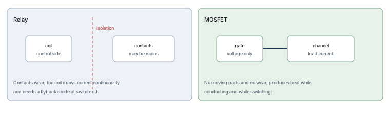
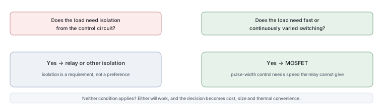
The choice between a relay and a MOSFET usually comes down to one question that has nothing to do with performance: does the load need to be electrically isolated from your control circuit? Where it does, the relay wins outright. Where it does not, the MOSFET usually wins on everything else.
Two ways to switch a load
A relay is an electromagnet operating a set of contacts. Current through a coil pulls an armature, the armature moves the contacts, and the load circuit opens or closes. Because the coil and the contacts are physically separate, they can be at completely different voltages, which is the relay’s essential advantage.
A MOSFET is a semiconductor switch. A gate voltage creates a conducting channel, the load current flows through it, and there is no moving part and no separation between the control and the load. The analogy that fits is a light switch operated by a hand versus a valve operated by pressure: the first needs someone to reach it and wears with use, the second responds instantly and never wears, but it has no natural boundary between the pressure line and the lever.
Relay: isolation and a clicking sound
The relay’s strengths are worth stating precisely, because they are the reason it has not disappeared. The contacts provide genuine galvanic isolation, so a low-voltage controller can switch a mains-powered appliance without any electrical connection between the two. Contacts also have very low resistance when closed, so a relay can carry substantial current with almost no heat. And the part is simple and cheap in a wide range of ratings.
The weaknesses are equally specific. Contacts wear, and every operation consumes some of their life, which matters if the load switches thousands of times an hour. A relay coil draws continuous current while energised, which is significant in battery-powered projects. Switching is slow, so pulse-width control is impossible. And the coil generates a voltage spike when it is switched off, which is why a flyback diode is essentially mandatory.
MOSFET: silent and fast
A MOSFET switches in microseconds, draws almost no control current once the gate is charged, and can be switched indefinitely without wearing out. That combination makes it the only option for pulse-width control, where the load is switched on and off quickly to regulate average power — dimming an LED, controlling motor speed or regulating a heater.
Its costs are thermal and electrical. Heat is produced while it conducts and while it switches, so it needs a thermal path, and a poorly driven gate turns a good device into a hot one. It provides no isolation unless something else does, so a mains load requires additional measures. And its characteristic failure mode is a short circuit, which means the load is left switched on rather than off.
Switching speed and pulse-width control
Speed is where the comparison stops being a trade. A relay operates in milliseconds and its contacts will not tolerate rapid cycling; a MOSFET switches in microseconds and can be cycled continuously. If the project needs to regulate power by switching — dimming, speed control, temperature control, or any converter — only the semiconductor can do it.
It is worth being precise about what pulse-width control buys, because it is often described loosely. Switching a load fully on and fully off, quickly, produces the same average power as holding it partially on, but without the loss that partial conduction would create. That is why a MOSFET running at 50 per cent duty cycle is efficient while a transistor held half-on is a heater.
Heat and current limits
A closed relay contact has a resistance measured in milliohms, so a ten amp load produces almost no heat in the relay. A MOSFET conducting the same current has an on-resistance that produces measurable heat and rises with temperature, so the device has to be chosen and mounted with that in mind. For high currents the difference in thermal management is real: a relay rated for the current may need nothing, while a MOSFET may need copper, a heatsink or both.
The comparison inverts at low currents. A relay that has to switch a small signal still needs a coil, a driver and a flyback diode, whereas a small MOSFET needs nothing but a gate voltage.
| Property | Relay | MOSFET |
|---|---|---|
| Isolation between control and load | Yes, at the contacts | None |
| Switching speed | Milliseconds, and limited by wear | Microseconds, effectively unlimited |
| Pulse-width control | Not practical | The normal way to control power |
| Heat while conducting | Almost none | On-resistance loss, rising with temperature |
| Control current | Continuous coil current | Almost none once the gate is charged |
| Service life | Limited by contact wear | No inherent limit |
| Typical failure | Open circuit | Short circuit |
| Audible noise | A distinct click | None |
Cost, size and lifetime
At low currents the MOSFET is smaller and cheaper once the surrounding circuit is counted, because no coil, no driver transistor and no flyback diode are needed. As the current rises, the comparison narrows: the MOSFET has to be larger to keep its resistance low, and the thermal hardware starts to cost more than a relay would.
Lifetime follows the same pattern. A relay used occasionally will outlast the product; a relay used for rapid switching will not. A MOSFET has no wearing part, but it does accumulate thermal fatigue if it is cycled between temperature extremes, so a poorly cooled semiconductor can have a shorter life than a lightly used relay.
Three external references are useful when checking the claims in this comparison. The relay is described under relays, its switch-off behaviour under flyback diodes, and the semiconductor alternative under MOSFETs. Device test methods come from JEDEC, thermal and assembly expectations from IPC, electrical installation and safety standards from the International Electrotechnical Commission, and sector-level context from the Semiconductor Industry Association. Device and quality background is published by ISO and NIST.
One practical detail about relays deserves a sentence, because its absence causes a large share of failed hobby builds. A relay coil is an inductor, and interrupting the current through an inductor produces a voltage spike that will destroy the transistor driving the coil. A diode connected across the coil, oriented so that it is reverse biased while the coil is energised, gives the stored energy somewhere to go. Omitting it produces a project that works for a while and then stops working, usually at the moment the load switches off.
A project-based decision table
| Your situation | Reach for | Because |
|---|---|---|
| Switching a mains appliance from a low-voltage controller | A relay or an isolated alternative | Isolation is required, not optional |
| Dimming an LED or controlling motor speed | A MOSFET | Pulse-width control needs speed the relay cannot provide |
| Switching a load a few times a day | Either; the relay is simpler | Contact wear is irrelevant at that rate |
| Battery-powered project switching frequently | A MOSFET | Coil current would drain the battery continuously |
| Loads above a few amps with modest switching | Often a relay | No thermal design needed at the switch itself |
| Any circuit where an accidental short would be dangerous | Whichever fails safe in your design | A MOSFET usually fails short and leaves the load on |
Safety notes
Two points matter more than any performance comparison. First, if the load is mains-powered and you are not using a relay or another isolating device, your low-voltage circuit now shares a reference with the mains, which makes the whole project hazardous to touch and to test. That is not a subtlety; it is the reason the isolation requirement comes first.
Second, the failure modes differ in a way that matters for design. A relay contact that fails open leaves the load off, which is usually the safe outcome. A MOSFET that fails short leaves the load on, which for a heater, a motor or a lamp can be worse than the original fault. Where that matters, the design needs a separate protection such as a fuse or a thermal cut-out, and the choice of switch does not remove that requirement.
FAQ
Why use a MOSFET instead of a relay?
For speed, silence, longevity and control efficiency. A MOSFET can switch thousands of times a second, which enables dimming, speed control and power conversion; it draws almost no control current; and it has no contacts to wear. If none of those matter for your project and isolation does, the relay is the better answer.
Can a MOSFET be used as a relay?
It can replace a relay wherever the load shares a common ground with the control circuit or where isolation is provided by something else. It cannot replace a relay’s isolation, because a MOSFET has an inherent electrical path between its control side and its load. Where a project uses a MOSFET in a position that had a relay, the isolation is usually being provided by an optocoupler or a separate supply rather than by the switch.
Is a MOSFET just a transistor?
Yes — it is one of the main transistor families, distinguished by being controlled by a voltage at an insulated gate rather than by a current. Our article on what a MOSFET is explains the mechanism in plain language.
What kills MOSFETs?
Gate overvoltage, which destroys the thin oxide layer almost instantly; overheating from excessive current or inadequate cooling; avalanche events beyond the rating; and shoot-through in bridge circuits where two devices conduct simultaneously. In practice most failures are application problems, which is why a replacement device usually fails too unless the cause is found first.
Which one should I use for a first project?
If the load is low-voltage — an LED, a small motor, a fan — use a MOSFET, because it needs no coil, no flyback diode and no driver, and it lets you experiment with pulse-width control immediately. If the load plugs into mains, build the project with a relay or do not build it yet, because the safety questions are a separate skill that deserves its own study.
What to do next
Write down three things about your project: the load voltage, whether the load shares a ground with your control circuit, and how often the switch will operate. Those three answers resolve the relay-or-MOSFET question in almost every case, and they are also the three questions a designer asks first. If the answer is a MOSFET, our article on what a MOSFET is covers the drive requirements that decide whether it will run cool.
Tell Good-Ark the load voltage, the current and how often it switches, and we can point to the device family and package that carry it without running hot.
Email sales@goodark.com, or start from the product family learning centre.
This article is published by Good-Ark, a manufacturer of MOSFETs and other discrete devices. It compares switching technologies rather than specific products, and it does not provide instructions for mains wiring, which is governed by local regulations and belongs to qualified people.
Recommended
 Why Do Diodes Get Hot? Conduction and Switching Losses ExplainedInfoStandard, Fast Recovery, and Schottky Diodes: What’s the Difference?Info
 What Is a Fast Recovery Diode? Understanding “Fast Recovery”Info
 What Is a Diode? A Beginner’s Guide to How It WorksInfo
 Automotive Semiconductor Report 2026: Chips Per Car Keep RisingKnowledge