Power Supply Application Design Hub
Power supply hub: how a supply converts power, designing conversion stages and supporting circuits, and tracing symptoms to check operation.
26 guides
Find the guide for the power stage or symptom you are working on: an adapter, switching supply, server rail, lighting driver or noisy output. Use the system guides first, then move to the component and diagnostic references.
Jump to the article collection
Power supply design: connect the source, conversion stage and load
A power supply converts an available input into the electrical output required by a load. Rectification, switching, energy storage, feedback and protection can all be part of that task, but they are different functions. A bridge rectifier produces a single-polarity waveform; a capacitor can smooth it; regulation controls the output within specified limits. Recognizing those roles makes a schematic easier to understand and prevents one component from being credited with the work of the whole supply.
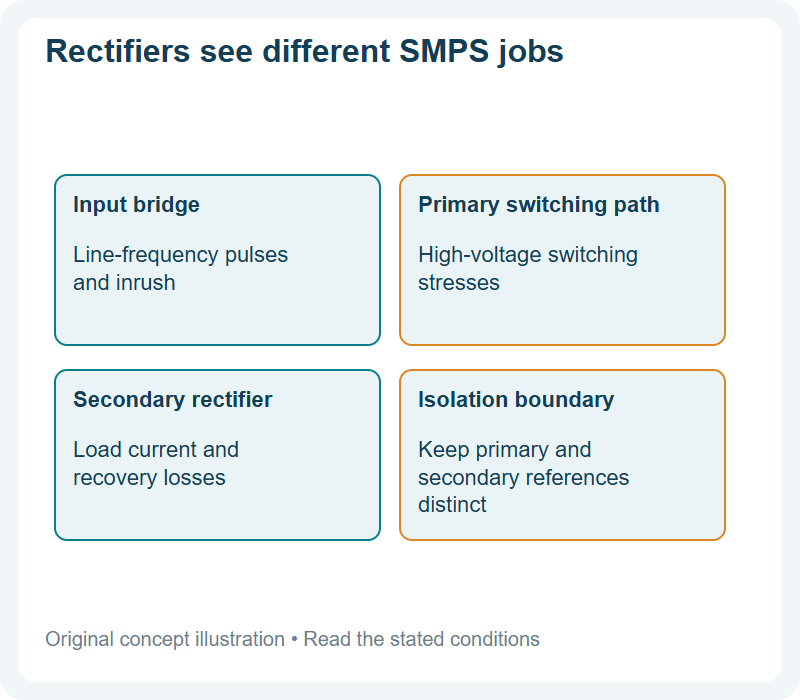
This hub follows the complete power path before narrowing into individual semiconductors. Begin with the input range, output requirement and load behavior. Then identify the conversion architecture and the stresses at each position. A diode on the input bridge, a secondary rectifier and a small feedback component may appear in the same enclosure while facing very different waveforms. Their ratings should be selected from those local conditions rather than from the supply's total wattage alone.
Linear and switching supplies manage energy differently
A linear regulator controls the voltage difference across a pass element, with the resulting dissipation set by its operating conditions. It can be useful where the input-to-output difference, current and thermal requirements are compatible with that approach. A switching converter transfers energy through controlled switching and storage elements, allowing different conversion relationships while introducing ripple, switching loss and control considerations. Neither description establishes the best architecture without the actual requirements.
Isolation is a separate question from whether a supply switches. An isolated converter provides a defined separation between input and output through its complete construction, while a non-isolated circuit shares an electrical relationship across those sides. Do not infer that a low output voltage is safe to touch without understanding its reference to the input. The transformer, insulation system, layout and protective construction must be considered as an assembly, not inferred from one schematic symbol.
Assign each semiconductor a circuit role
The input rectifier handles the waveform delivered by the source and any charging pulses drawn by downstream capacitance. A switching transistor controls energy transfer and sees voltage, current and transition stresses set by the topology. An output rectifier or synchronous switch conducts during another part of the cycle. Clamps and snubbers manage specified transient behavior, while control and feedback components establish how the system responds to changing conditions.
Write the important waveform beside each position before shortlisting devices. Include reverse blocking or drain voltage, current shape, switching conditions and the expected temperature. A high current rating under ideal cooling is not the same as acceptable operation on the available PCB. A fast diode may reduce a recovery-related loss but introduce different capacitance or leakage behavior. Selection is a set of related local decisions within one overall efficiency and reliability target.
Startup and changing loads reveal hidden requirements
Steady operation is only one part of a supply's life. Charging an initially empty capacitor can create a demanding current event. A sudden load change can challenge the feedback loop and output storage. Startup with a heavy load, repeated power cycling and operation near the edge of the input range can expose stresses that are absent in a nominal bench reading. Define those states before deciding what measurements establish success.
Protection should have a clear response for overload, short circuit and other relevant faults. Limiting current, shutting down and repeatedly attempting restart can place different demands on semiconductors and magnetics. Consider where stored energy goes when switching stops. A clamp that survives one brief pulse may not tolerate repeated fault cycling without cooling. The control behavior and the power components therefore need to be evaluated together during abnormal operation.
Efficiency, temperature and interference interact
Efficiency describes the relationship between delivered output power and input power under a stated condition. Lost power becomes heat in several parts of the supply, not only in the main switch. Rectifier conduction, switching transitions, magnetic components, resistive paths and control consumption can all contribute. Measure or estimate the important terms before changing the component that happens to feel hottest; its temperature also reflects its heat path and surroundings.
Faster switching transitions can reduce some losses while increasing ringing or electromagnetic disturbance. Filtering and snubbing may improve behavior while adding size or dissipation. Layout influences those tradeoffs by setting the high-current loops and coupling paths. Compare designs at the same input, output and thermal conditions, and include any changes needed to achieve acceptable interference and stability. A device-level improvement that forces larger losses elsewhere may not improve the finished supply.
Compare at more than one operating point
A supply selected for maximum output may spend much of its life lightly loaded or waiting for a demand signal. Behavior at low load, during standby and through transitions can affect the actual application as much as the full-load result. Define the relevant operating points before comparing efficiency or temperature. Keep the input range, output setting, enclosure and measurement method consistent so that differences can be attributed to the design rather than to a changed test setup.
Diagnose by following the power path
When a supply has no output, excessive ripple or abnormal heating, identify where the expected behavior first disappears. Check the source and input protection before blaming the output stage. Distinguish a missing control drive from a switch that receives a correct drive but fails to transfer energy. Inspect connections and loads as well as semiconductors. A fault downstream can repeatedly damage an otherwise correctly specified upstream part.
Measurements on mains-connected or stored-energy circuits require appropriate equipment and procedures. A general-purpose meter or earth-referenced oscilloscope connection can be unsuitable for a particular node. The guides below explain circuit operation, component selection and symptom-based investigation at different levels. Use them to build a record of input conditions, load state, waveforms and temperature so that a repair or design change can be evaluated against evidence rather than a single output-voltage reading.
Understand the complete power supply
Start with the conversion path and the components inside a familiar power source.
How a Power Adapter Turns Wall Power Into 5 V: A Guided Tour
A modern power adapter does not simply step the mains voltage down; it chops it, transfers it across a small transformer and rebuilds it on the other side. That is why the box is small, why it works on…
Inside a Switching Power Supply: The Component Roles That Make or Break Efficiency
A switching power supply looks like a box of unrelated parts until you see the jobs. Five component types — the switch, the transformer, the rectifier diode, the output capacitor, and the controller — carry…
What Are SMPS Components and Their Functions?
An SMPS, or switched-mode power supply, converts electrical power efficiently using a coordinated set of parts that rectify, switch, transform, filter, protect, and regulate voltage. The main components…
What Is a Switching Power Supply? How SMPS Works
A switching power supply converts electrical power by repeatedly switching semiconductor devices on and off, transferring energy through inductors, transformers or other storage elements. A feedback controller…
What Is an Isolated Power Supply?
Isolated power supplies explained: why isolation matters, which topologies suit which power level, and the design choices that decide safety and EMI.
What Is Inside a PC Power Supply? A Beginner’s Teardown Guide
A desktop power supply converts the alternating current from the wall socket into three steady direct voltages that the computer uses: 12 V for the processor and graphics card, 5 V and 3.3 V for the rest. It…
What Is Inside a Power Bank?
Inside a power bank there are four blocks: cells that store energy, a converter that changes the cell voltage into the voltage your device expects, protection circuitry that keeps the cells inside their safe…
Energy Efficiency Rules Worldwide: How Regulations Shape Component Choices
See how energy-efficiency requirements influence standby loss, conversion stages and component choices.
AC vs DC Explained: Why Diodes Are the Bridge Between Your Wall Socket and Your Phone
Follow AC-to-DC conversion from the wall supply through rectification and the phone power path.
Design conversion stages and supporting circuits
These guides connect the converter application to the component and circuit decisions around it.
Designing a Dashboard Cluster Power Stage With AMBRB3045CT
The dashboard cluster’s power stage is a budget-driven design: the displays, audio, and logic each draw current, and the AMBRB3045CT—a 30 A, 45 V common-cathode Schottky in D2PAK—serves the buck outputs and…
Flyback Snubber Design: Taming the Diode Ringing and the Voltage Spike That Follows
Every switch cycle in a flyback converter ends the same way: the switch turns off, the leakage energy in the transformer releases, and the output rectifier rings like a struck bell. The spike and the…
How Do LED Bulbs Work, and Why Do They Last Longer?
An LED bulb makes light by passing current through a semiconductor junction, which converts some of the electrical energy directly into photons instead of heating a filament until it glows. That is the reason…
How Do You Design an EMI Filter?
A switching power supply EMI filter design reduces conducted noise, improves EMC compliance, and protects the power line from switching spikes. The best design starts by identifying whether the noise is…
Industrial Applications of Power Semiconductors: Drives, UPS and Process Equipment
Industrial applications of power semiconductors include motor-speed control, regulated power supplies, backup conversion, welding, induction heating and battery formation. The devices switch, rectify or direct…
Power Package Thermal Design: From Rth(j-a) to Junction Temperature
This guide is the shared reference for the thermal method used across the Good-Ark package and device articles. It explains the thermal chain, the board design levers, and the measurement discipline, so the…
Reverse Recovery in SMPS Diodes: The Current Overshoot You Have to Design Out
The stored charge in a diode junction is a time bomb that releases every time the diode turns off. In an SMPS switching at high frequency, that release happens thousands of times per second, and each release…
TO-277 (eSGC) Footprint and Thermal Design Guide
The TO-277 (eSGC) package is the automotive board-level 5 A workhorse, and its exposed pad is the thermal contract: the pad, the vias, the copper, and the stencil decide whether the package performs to its…
GaN in AI Data Center Power: Rack PSU Trends and the Discrete Parts Around Them
Locate GaN conversion stages in AI rack power systems and identify the surrounding discrete components.
Switch Mode Power Supply: Semiconductor Selection Guide for B2B Buyers
Build a semiconductor sourcing checklist for an SMPS program using approved circuit ratings and documents.
Switching Mode Power Supply: Component Selection and Project Validation
Choose discrete components by power-stage waveform and validate efficiency, thermal and EMI behavior.
Trace symptoms and check operation
Use these references to connect a measurement or symptom with the stage that needs investigation.
Data Center and High-Efficiency Power Supply Architectures: An Industry Report
Data center power is moving toward higher PSU efficiency levels, 48V rack buses, and higher power per server, and the AC-DC input stage carries the consequences in voltage, current, and thermal duty. This…
Energy Storage Power Electronics in 2026: PCS, Battery Racks, and Protection
Energy storage systems are converging on DC-coupled architectures, battery racks in the 800–1500 Vdc range, and bidirectional power conversion, and each choice defines what the power semiconductors must carry.…
MEMS Sensors: Enabling Precise Motion in Power Electronics
MEMS sensors turn motion into signals. What the datasheet parameters mean for supply rails, noise budget and interface in a power-electronics design.
Power Supply Repair Workflow: Safety, Isolation, and the Component Test Order That Saves Time
Repairing a power supply is not a parts-drawer exercise; it is a sequence, and the sequence starts with safety. The order of actions — discharge, isolate, limit, test — is what separates a safe repair from a…
Ripple and Noise on Power Rails: Symptom-to-Source Troubleshooting in Five Checks
Most “ripple problems” on power rails are not ripple problems at all — they are measurement problems, layout problems, or load problems wearing a ripple costume. The scope shows a noisy rail, the engineer…
SMPS vs Linear Power Supplies: Efficiency, Noise, and the Trade You Actually Pay For
One trades heat for noise. That sentence is the whole story of linear versus switching power supplies, because every difference between the two topologies traces back to whether they convert the line power…
GaN Charger Market Report
Where GaN chargers change SMPS topology choices and which silicon discretes still matter.
Need help with a particular circuit?
Include the circuit position, operating conditions and the part number or marking when you contact Good-Ark technical support.
Recommended
 SMPS Rectifier Diode Selection: Primary vs Secondary JobsKnowledge
 Ohm’s Law for Diode Circuits: Drop, Dissipation, Sanity ChecksKnowledge
 How to Discharge a Capacitor Safely Before Probing BoardsKnowledge
 Boost Converter Explained: Inductor Kick and Diode PathKnowledge
 Buck Converter Basics: Switch, Diode, and Inductor RolesKnowledge
 PWM Duty Cycle Explained for Power and LED ControlKnowledge