Reverse Polarity Protection Diode: Selecting the Right Device for Reliable Power Entry Protection
A reverse polarity protection diode blocks a backward supply at the cost of a permanent forward drop. How to work out the watts and choose the device.

The counter-intuitive part of reverse polarity protection is that the diode usually is not the cheapest way to protect a high-current input — it is the simplest way to protect a low-current one. A series Schottky blocks the fault for the price of a forward drop, and at 2 A that drop is roughly a watt of permanent self-heating; a low-resistance switch blocks it for a fraction of that, at the cost of a control arrangement. Choosing between them is an arithmetic question about current, not a matter of preference.
Last updated:
Key Takeaways
- A reverse polarity protection diode sits at the power entry and blocks a backward-connected supply before the load sees it — the fault it prevents is a wiring error, not a transient.
- Its cost is a permanent forward drop. Multiply the drop by the load current to get the watts, then use the package’s thermal resistance to get the junction rise.
- Series Schottky versus low-resistance switch versus bridge is a genuine trade: drop against complexity, and both against reverse-blocking behaviour during the fault.
- Small-signal families are signal-level parts. In the ST BAT54 datasheet the specified junction-to-ambient thermal resistance is 500 °C/W for SOT-23, so even 90 mW costs a 45 °C rise.
- Verify the reverse-voltage rating against the worst case at the input, and check leakage at the hot end of the temperature range rather than at 25 °C.
The Options on the Table
There are three common ways to block a reversed input, and they differ mainly in what they cost you while the supply is correct. That last clause is the one that decides real designs, because the protection only acts once.
| Approach | What it costs in normal operation | What it costs in design effort | Where it fits |
|---|---|---|---|
| Series Schottky diode | A fixed forward drop at all currents, and the heat that drop generates | Almost none: a two-terminal part in the input path | Low- and moderate-current inputs where rail margin is generous |
| Series switch with low on-resistance | A voltage drop proportional to current squared, but small at the currents it is sized for | A gate or enable arrangement that turns the switch on for the correct polarity | Higher-current inputs where a diode drop would waste meaningful power |
| Bridge or arrangement that accepts either polarity | Two diode drops in series in the conducting path | More devices and more board area | Products where the connector can genuinely be reversed by the end user |
The first row is where most designs start and where many stop. It is not a mistake as long as the arithmetic has been done: a diode drop that costs 5 % of the rail is a design choice, and one that costs the regulator its dropout margin is a defect waiting for a cold day.
Doing the Arithmetic Before Choosing
Two multiplications decide the device: drop × current for the power, and power × thermal resistance for the rise. Both are visible on a datasheet, and neither takes long.
The published figures for a small-signal dual Schottky family illustrate the scale. In the ST BAT54 datasheet the maximum forward voltage is 900 mV at 100 mA and the junction-to-ambient thermal resistance is 500 °C/W in SOT-23. So even at 100 mA, a modest signal-level current, the dissipation is 90 mW and the junction sits 45 °C above ambient — comfortable at room temperature, and 20 °C from the 150 °C limit when the board lives at 85 °C. Running this family at an amp or more is not a marginal decision; it is outside the specification entirely.
The same arithmetic on a larger input is what pushes a design toward a switch. A 2 A load through a 0.5 V drop dissipates 1 W continuously. Through a switch with 20 mΩ of on-resistance, the same 2 A dissipates 2 A × 2 A × 0.020 Ω = 80 mW, more than an order of magnitude less. These are stated assumptions, not measured results — substitute your own drop and on-resistance at the current and temperature the design will actually reach — but the ratio is what drives the topologies you see in higher-current equipment.
| Load current | Loss with a 0.5 V drop | Loss with 20 mΩ on-resistance | Practical reading |
|---|---|---|---|
| 100 mA | 50 mW | 0.2 mW | A diode is simple and acceptable; a switch is over-engineering |
| 1 A | 500 mW | 20 mW | Diode heat is now a layout constraint |
| 2 A | 1 W | 80 mW | Diode loss dominates the entry stage; a switch is usually the better answer |
Boundary Conditions That Decide Whether It Survives
Three boundaries separate a part that blocks the fault from one that is damaged by it. Each is a datasheet line, and each is routinely skipped.
The first is reverse voltage. The diode has to withstand the highest reverse voltage the input can present, which is not always the nominal rail: a reversed supply on an inductive or battery-fed input can exceed the nominal value, and an automotive input adds transient events on top. Choose the rating from the worst case and derate from there. The second is leakage at temperature: a small-signal Schottky specified at 1 µA at 25 °C can be specified at 100 µA at a 100 °C junction, which matters on a high-impedance or battery-backed node. The third is surge, where the device must handle the inrush of charging the input capacitance without exceeding its non-repetitive current rating.
Package and thermal layout complete the picture. A reverse polarity device sits at the entry point, where board space is tight and copper may be scarce, and the thermal resistance in the datasheet assumes a defined pad area. Shrinking that area quietly invalidates the temperature rise you calculated.
What to Put in the Approval File
Make the selection reviewable by asking for documents rather than assurances. For an entry-stage protection device that means the datasheet for the exact part with its forward-voltage and derating curves; the package and outline drawing; the reverse-voltage and leakage figures at the hot end of the temperature range; surge or inrush ratings; and, where the product is automotive, the AEC-Q101 qualification report for the exact part together with the quality-system evidence for the site that made it.
If the application has to tolerate a genuinely reversible connector or an automotive transient profile, say so before requesting parts rather than after qualification: those requirements change which topology is appropriate, and they are much cheaper to accommodate at selection than at validation.
FAQ
Does a diode protect against reverse polarity?
Yes, in the most common form: a series diode at the input blocks current when the supply is connected backward, so the load never sees the reversed voltage. The trade is a forward drop and the heat that drop produces during normal operation.
What is the cheapest way to protect a low-current input?
A single series Schottky diode. At signal-level currents the drop generates milliwatts, and the part adds no control circuitry, no gate drive and no quiescent current.
At what current should I stop using a series diode?
When the loss becomes a thermal constraint rather than a line item. Work it out: multiply the forward drop by the load current, then multiply that by the package’s junction-to-ambient thermal resistance. If the resulting rise eats your margin, move to a low-resistance switch.
Why is a bridge sometimes used instead of a single diode?
Because a bridge accepts either input polarity, which suits products where the connector really can be reversed by the user. The cost is two diode drops in the conducting path instead of one, so it loses the efficiency argument whenever the polarity is known.
What happens if you exceed the diode’s reverse voltage rating?
The device may enter breakdown and conduct in the reverse direction, which defeats the protection and can damage the part. Choose the rating from the worst-case input, including transients, and keep derating margin rather than running at the absolute limit.
Related Articles
- Schottky barrier rectifier diode: practical selection
- General-purpose rectifier diodes for 50/60 Hz supplies
- Automotive rectifier diodes: transient protection and AEC-Q101
- Reverse polarity protection in BMS: diode vs ideal-diode MOSFET
- Talk to a Good-Ark engineer
Official Resources
- Good-Ark rectifier and protection device families
- Good-Ark package and outline dimensions
- Good-Ark qualification certificates
References
- STMicroelectronics, BAT54 — Small signal Schottky diodes, DocID5505 Rev 12 — source of the 900 mV maximum forward voltage at 100 mA, the 500 °C/W SOT-23 thermal resistance, and the reverse leakage figures at 25 °C and 100 °C. st.com/resource/en/datasheet/bat54.pdf
- Analog Devices, Reverse-Current Circuitry Protection — design note on protecting circuits against reverse current paths and the behaviour of blocking elements. analog.com — reverse-current circuitry protection
- Diodes Incorporated, 1N4001–1N4007 1.0 A Rectifier, DS28002 Rev 11–3 — source of the automotive qualification statement (AEC-Q100/101/104/200, PPAP capable, IATF 16949 certified facilities) and of the 1 A rectifier class reference. diodes.com/assets/Datasheets/ds28002.pdf
- IEC 60664-1 — insulation coordination for equipment within low-voltage supply systems, the reference for creepage and clearance questions at the input stage. webstore.iec.ch/en/publication/59671
Continue through this engineering topic
For the complete selection, design, verification, and troubleshooting path, explore the TVS ESD and Surge Protection Hub.
- Practical guide: Transient Voltage Suppressor: Protect Electronics From Lightning, ESD, and Switching Surges
- Practical guide: Protecting USB Ports From Static: A Beginner’s Guide
- Practical guide: Clamping Voltage Explained: The Datasheet Number That Decides Protection
- Ask Good-Ark technical support about this application
Recommended
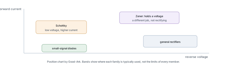 The Diode Part Numbers Everyone Eventually Meets: 1N4007, 1N4148, SS14 and FriendsKnowledge
 What Does the GS Prefix Mean? Decoding MOSFET Part Numbers Without GuessingKnowledge
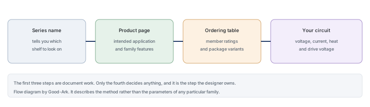 What Is the GSMDJ Series Used For? A Beginner-Friendly ExplanationKnowledge
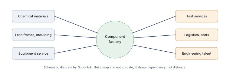 Suzhou Good-Ark: Why a Component Maker’s Home City Matters More Than You ThinkKnowledgePV Bypass Diode Failures in the Field: Hot Spots and Thermal StressInfoHow to Select a PV Bypass Diode: VF, Leakage, Surge, and the Junction BoxInfo