What Is a Switching Power Supply? How SMPS Works
A switching power supply converts electrical power by repeatedly switching semiconductor devices on and off, transferring energy through inductors, transformers or other…

A switching power supply converts electrical power by repeatedly switching semiconductor devices on and off, transferring energy through inductors, transformers or other storage elements. A feedback controller adjusts the switching behavior to maintain the required output. SMPS means switched-mode power supply; it can take AC or DC input, depending on its design.
The familiar examples are laptop adapters, phone chargers and PC power supplies. A small DC-to-DC buck converter is also a switching supply, even though it has no mains input and may have no transformer. What connects these products is the conversion method.
How does a switching power supply work?
It regulates energy delivered in repeated switching cycles.
The power stage handles energy, while the controller responds to the output and operating conditions. The exact current paths depend on the converter topology.
Consider a buck converter reducing a DC voltage. During one interval, a switch connects the input to an inductor and the output. During another, current continues through a diode or another controlled switch. The inductor and capacitor reduce the pulsating behavior so the load receives a steadier output.
Texas Instruments’ buck and boost topology guide describes these current paths. “Switching” does not mean the output simply turns fully on and off; the storage elements and regulation loop make the conversion useful.
A real switch has conducting resistance and takes time to change state. It can therefore dissipate power both while on and during transitions. Treating the device as a perfect switch is helpful for learning the principle, but insufficient for predicting temperature or efficiency.
Last updated:
What happens inside an AC-input SMPS?
An AC-input design first creates an internal DC supply.
A common isolated arrangement then switches that DC, transfers energy across an isolation barrier and produces a filtered output. Some designs use additional or different stages.
The input network can include filtering, rectification, inrush control and a bulk capacitor. A separate power-factor-correction stage may shape the input current. The switching stage and magnetics perform the main conversion; output rectification or synchronous switching and capacitors produce the output rail.

DC-input converters start from an existing DC source and do not need the same AC front end. A non-isolated buck converter may use an inductor without any isolation transformer. Avoid turning one offline-adapter diagram into a description of every switching supply.
Tektronix’s switching-power-supply overview provides a broader introduction. For the component families carrying current in these blocks, see our discrete power device guide.
How does the controller keep the output stable?
Feedback adjusts conversion when input or load changes.
The controller compares a measured quantity with a target and changes the power-stage operation. Pulse-width modulation is common, but it is not the only control method.
Duty cycle is the fraction of a switching period during which a specified switch is on: D = t_on / T. For an ideal buck converter in continuous conduction, V_out ≈ D × V_in. An illustrative 12 V-to-5 V conversion would require a duty cycle near 5/12, or 41.7%.
This simplified relationship ignores losses and does not describe every topology or operating mode. Some controllers change frequency, skip pulses or enter burst operation at light load. Others use resonant operation, where control cannot be reduced to the same buck equation.
An isolated converter may send feedback through an optocoupler or another isolation method, or regulate using information available on the primary side. Isolation and feedback implementation are separate design choices. A supply also needs a stable response to load steps; accurate steady-state voltage alone does not prove good transient behavior.
Which switching-supply topologies should you recognize?
Recognize the topology by its conversion and isolation needs.
Start with the input range, desired output and isolation requirement. A named topology is a starting point, not a guarantee of efficiency or a fixed power capability.
| Topology | Basic task | Typical consideration |
|---|---|---|
| Buck | Non-isolated step-down | Input remains above output within design limits |
| Boost | Non-isolated step-up | Output normally exceeds input |
| Buck-boost | Step up and down | Polarity and current paths depend on implementation |
| Flyback | Energy storage and transfer; commonly isolated | Peak currents, leakage energy and ripple |
| Forward or bridge-derived | Transformer-based power transfer | Reset, drive and magnetic design |
| LLC resonant | Conversion through a resonant network | Gain range and soft-switching conditions |
A flyback deserves a distinction: it stores energy in its coupled inductor during the primary switch’s on interval and transfers energy to the secondary during the off interval. TI’s flyback explanation shows the operating sequence.
Do not select a topology solely from a published wattage band. Magnetics, cooling, operating range, interleaving and controller choices can move practical boundaries.
How does an SMPS compare with a linear supply?
Switching conversion often reduces loss at large voltage drops.
Linear regulation can be simpler and quieter, especially with a small input-to-output difference. Neither method is universally better for every load.
A linear regulator dissipates approximately (V_in − V_out) × I_out, ignoring its own supply current. For a hypothetical 12 V input, 5 V output and 1 A load, that means 7 W of regulator heat while delivering 5 W. The idealized efficiency is 5/12, or about 41.7%.
Now consider 5.5 V to 5 V at the same current: the idealized regulator efficiency becomes about 90.9%. This is why a single low-efficiency percentage is a poor description of all linear regulators.
| Question | Switching conversion | Linear regulation |
|---|---|---|
| Large voltage reduction | Often substantially lower loss | Heat increases with voltage difference |
| Noise | Switching ripple and EMI require attention | No switching node within the regulator |
| Circuit complexity | Control, layout and passives matter | Can be relatively simple |
| Step-up operation | Available with suitable topology | Not provided by a basic linear regulator |
Matsusada’s supply comparison explains the practical trade-offs. Complete supply architectures may also combine switching conversion with a linear post-regulator.
What determines efficiency, heat and noise?
Performance depends on the complete design and operating point.
Check measured efficiency across input voltage and load. A favorable peak figure does not describe standby consumption, light-load behavior or the hottest operating condition.
Define efficiency as η = P_out / P_in. If a hypothetical supply delivers 60 W at 90% efficiency, it needs about 66.7 W input and dissipates about 6.7 W in total. At 95%, the corresponding loss is about 3.2 W. These calculations compare assumed operating points; they are not product performance claims.

Switching edges also excite parasitic inductance and capacitance. Filters, layout and controlled transitions help manage conducted and radiated noise. Faster switching can reduce some losses while making other problems harder; it does not automatically make a quieter supply.
Power factor is a separate input-quality measurement. High efficiency does not prove high power factor, and adding a component with a favorable specification does not certify the complete supply.
What should you check before buying or connecting one?
Match the output and interface to the actual load.
Begin with voltage, polarity, current requirement and input range. Then check isolation, ripple, transient response and operating-temperature limits.
- Confirm the exact output voltage and connector polarity.
- Check continuous and startup current against the supply specification.
- Verify input frequency, voltage range and any selector setting.
- Review ripple, load-step response and protection behavior.
- Check the installation, cooling and required isolation or approvals.
A higher current rating can be acceptable for a normal constant-voltage load when voltage and interface match; it does not force that maximum current into the load. However, constant-current LED drivers, negotiated USB power and other specialized interfaces need their own compatibility checks.
For a mains unit, do not identify the architecture by opening it while powered. Stored charge can remain after disconnection. Use the label, manual and manufacturer documentation; internal measurements require appropriate skills and equipment.
FAQs
Does “switching” mean it is controlled by an external on/off switch?
No. It describes the rapid internal switching used for energy conversion. A product may also have a separate user power switch, but that is not what makes it an SMPS.
Can a switching supply be used for audio equipment?
Yes, when its ripple, interference, grounding and transient behavior meet the equipment’s needs. The architecture name alone does not establish whether audible noise or interference will occur.
Is an SMPS always isolated?
No. Many DC-to-DC switching converters are non-isolated. Confirm the specified isolation barrier and intended application rather than assuming that a switching supply includes a transformer.
Can a buzzing sound identify a failed supply?
Not by itself. Audible vibration can occur under some operating modes, but unexpected noise can also accompany an overload or fault. Follow the manufacturer’s troubleshooting instructions and check whether output behavior remains within specification.
What is the most useful next check?
Write down what the load requires before choosing a supply. Match voltage and interface first, then verify current, noise, isolation and cooling. For component-level design, use the topology and measured waveforms to guide semiconductor selection; our SiC guide covers one possible technology choice without making it mandatory.
Continue through this engineering topic
For the complete selection, design, verification, and troubleshooting path, explore the Power Supply Application Design Hub.
Recommended
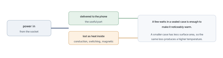 Why Does Your Phone Charger Get Warm?Knowledge
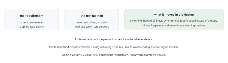 Energy Efficiency Rules Worldwide: How Regulations Shape Component ChoicesKnowledge
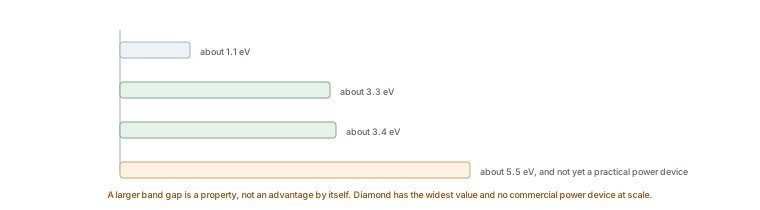 Wide-Bandgap Semiconductors: Adoption Report 2026Knowledge
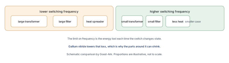 The GaN Charger Market: Why Your Next Adapter Is SmallerKnowledge
 Component Lead Times in 2026: What Is Actually Normal NowKnowledge
 China’s Power Semiconductor Industry: Where It Stands in 2026Knowledge