ES1J and UF5408: Picking a Fast or Ultrafast Axial Rectifier
The faster-looking part can be the more expensive change, even when no component price is considered. An ES1J diode in the reference…
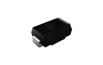
The faster-looking part can be the more expensive change, even when no component price is considered. An ES1J diode in the reference below is surface mount; the UF5408 is axial. Moving between them changes the footprint, assembly method, and heat path before any electrical comparison begins.
These devices use different mounting styles. Use the comparison to separate recovery requirements from mounting and current capability, then count the practical work involved in a substitution.
ES1J diode and UF5408: what the choice really involves
The referenced ES1J is a 600 V surface-mount SMA rectifier, while the referenced UF5408 is a 1000 V axial DO-201AD rectifier with a different current rating. Both have documented fast recovery. Select by waveform, recovery conditions, losses, mounting, and cooling; their names do not establish drop-in electrical or physical interchangeability.
The numerical sources are the Nexperia ES1J datasheet, January 2025 and Vishay UF5400–UF5408 datasheet. Their values belong to those manufacturers and documents. Verify another supplier’s exact part independently.
Separate the cost of conduction from the cost of changing the board
Conduction loss depends on the operating current and forward characteristic. Recovery-related loss depends on the switching event and the surrounding circuit. Neither can be judged from package size or the word ultrafast alone.
The implementation effort is different. An SMA part needs the correct pads, solder process, and board thermal path. An axial part needs suitable hole spacing, lead forming, body clearance, and mounting conditions. A hand-wired adaptation can change inductance and mechanical support, so it is a design change rather than a neutral way to make the part fit.
Keep those effort categories separate in the decision record: electrical analysis, board change, assembly change, thermal validation, and operating checks. A nominally capable diode may still create more redesign work than selecting a compatible package with the required specification.
A selection sequence before ordering either device
Start from the waveform and the existing mounting arrangement. A hobby repair on an axial board and a new automated surface-mount design have different practical constraints, even when both need a fast rectifier.
- Identify the original diode’s function and full manufacturer part number.
- Determine reverse stress, including overshoot and startup.
- Record average, RMS, peak, and surge-current requirements where relevant.
- Compare recovery conditions and the expected commutation event.
- Estimate forward loss and check the installation’s cooling path.
- Review the package drawing, footprint, and assembly process.
- Validate the proposed change before treating it as an approved substitute.
If a required package change defeats the repair’s practical constraints, select another candidate rather than forcing an electrically incomplete comparison between these two parts.
A table that keeps package and test conditions visible
The entries below are selected reference specifications. Current ratings use different thermal reference conditions; the recovery-time comparison uses matching stated current values. Consult the complete documents for notes and the full operating limits.
| Check | ES1J reference | UF5408 reference |
|---|---|---|
| Package | SMA, surface mount | DO-201AD, axial |
| Repetitive reverse voltage | 600 V | 1000 V |
| Average forward current | 1 A, 50% square wave at 20 kHz; solder point ≤136 °C | 3 A, 9.5 mm leads; ambient 55 °C |
| Maximum recovery time | 35 ns | 75 ns |
| Recovery-test conditions | Forward 0.5 A, reverse 1 A, endpoint 0.25 A; junction 25 °C | Forward 0.5 A, reverse 1 A, endpoint 0.25 A; junction 25 °C |
The shorter listed time does not independently establish lower installed loss. Forward behavior, recovery-current shape, circuit parasitics, and cooling also matter. A higher reverse rating likewise does not establish suitability for the actual current waveform.
Common mistakes that add rework
The first mistake is assuming ES1J is axial because it is compared with an axial family. Confirm the package in the actual datasheet and order code. A catalog heading or a search result is not enough to release a footprint change.
A second mistake is comparing current ratings without their thermal conditions. Solder-point temperature and ambient temperature are different quantities. A rating tied to one cannot be transferred to the other without a suitable thermal model and installation evidence.
A third mistake is treating the fastest timing number as the complete dynamic result. The onsemi recovery analysis explains the reverse-current waveform and its definitions. Abrupt current change and layout inductance can influence overshoot even when a timing entry looks favorable.
Verification checks that answer the actual circuit question
Begin with unpowered junction screening when diagnosing a removed part or a discharged board. Measure both directions and account for parallel connections. The Fluke diode-test procedure describes that basic method.
A normal reading does not measure recovery time or validate heat dissipation. Operating checks should address the current waveform, reverse overshoot, startup, and temperature under representative conditions. Preserve probe arrangement and load conditions when comparing candidates.
When the original failure occurred at power-on, include capacitor charging and the source impedance in the investigation. When it occurred after warm-up, inspect the thermal state rather than repeating only a cold start. Matching the test to the reported symptom helps prevent an electrically plausible replacement from returning with the same fault.
The Analog Devices flyback-diode article provides an example of topology-specific selection. Derive the actual stress terms for your circuit rather than copying another converter’s equation unchanged.

How the comparison connects to other discrete devices
A fast rectifier is not a specified transient suppressor. The TVS explanation and TVS versus Zener comparison separate blocking, clamping, and regulation roles. Do not interpret the reverse rating in this table as a clamp threshold.
The USB ESD protection guide adds the signal-integrity and array considerations of interface protection. For larger switching-power packages, the TO-247 fast-recovery discussion connects rectifier behavior with another mounting context. Those are separate design choices, not automatic substitutions.
A checklist for the practical cost of a change
List what must be changed and revalidated: pads or holes, mounting support, lead geometry, solder process, thermal path, and the measurement setup. Then compare the operating requirements against the exact candidate specification.
Check the available body clearance against neighboring parts and enclosure surfaces. Moving a diode above the board can change both support and clearance. Document the accepted arrangement with dimensions and mounting instructions if it becomes a retained design, rather than leaving the next operator to recreate it by eye.
Also consider documentation and repair repeatability. A one-off lead adaptation can be difficult for another technician to reproduce and may obscure the intended cathode orientation. If the change is retained, update the approved drawing and component identity so the next repair does not rely on a photograph alone.
When to stop and read the complete datasheet
Return to the source whenever package identity, current conditions, recovery definition, or thermal mounting is unclear. A comparison table should direct the next check, not conceal a missing guarantee.
The useful decision may be an axial rectifier with the required waveform performance or a surface-mount device designed into a suitable board. Choose the complete implementation that meets the requirements. Picking the smallest recovery-time number first can leave most of the engineering work unanswered.
FAQ
Is ES1J an axial diode like UF5408?
In the Nexperia reference used here, ES1J is an SMA surface-mount device, while the Vishay UF5408 uses an axial DO-201AD package. Verify the exact manufacturer and order code before changing a footprint. The axial wording in a comparison title should not replace the package drawing. Moving between these mounting styles changes mechanical, assembly, thermal, and potentially switching-loop conditions. Preserve that distinction in the replacement record.
Does the shorter recovery time make ES1J the better replacement?
Not by itself. Compare the relevant reverse voltage, current waveform, forward loss, recovery behavior, temperature, and package installation. A shorter timing value at compatible conditions answers one part of the review; it does not compensate for insufficient current capability or an unsuitable thermal path. Validate the complete proposed installation rather than ranking parts solely by a recovery-time number in a catalog.
Can I solder an axial diode across surface-mount pads for a repair?
Treat that as a design change requiring review, not a neutral substitution. Lead geometry, mechanical support, clearance, solder joints, thermal conditions, and loop inductance can all change. First establish that the candidate meets the circuit requirements, then assess whether the proposed mounting is acceptable and repeatable. Use an appropriately specified compatible package when an improvised adaptation cannot be validated for the application.
Recommended
 BAT46WS Small-Signal Schottky: Leakage, Vf, and Sensing UsesKnowledge
 FR107 and 1N5408: Choosing Higher-Current Axial RectifiersKnowledge
 UF4007 Diode: Ultrafast Sibling of the 1N4007 FamilyKnowledgeSS34 Schottky Diode (SMC): Specs and Board-Level FitKnowledge1N5819 Schottky Diode: Low-Voltage Uses and LimitsKnowledge
 MUR2060CT and MUR3040PT: Dual Ultrafast Rectifiers in Power StagesKnowledge