SS34 Schottky Diode (SMC): Specs and Board-Level Fit
The replacement reel says SS34, but the delivered body does not sit on the pads like the original. Even if a technician…
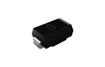
The replacement reel says SS34, but the delivered body does not sit on the pads like the original. Even if a technician can bridge the gap with solder, the substitution has already changed the mechanical and thermal installation. A matching base number has not established board compatibility.
For an SS34 Schottky diode, identify the manufacturer and package before comparing electrical headlines. This article uses a documented SMC version while showing why another supplier’s same-numbered device needs its own review.
SS34 Schottky diode: confirm the version before the fit
The referenced Vishay SS34 is a 3 A, 40 V Schottky rectifier in SMC, or DO-214AB, with ratings tied to stated conditions. Other manufacturers use SS34 for different packages. Confirm the exact order code, drawing, polarity, current waveform, reverse stress, and board cooling before approving an electrically or physically compatible replacement.
The numerical source is the Vishay SS32–SS36 datasheet. By contrast, MDD documents an SMA SS34. Do not combine their specifications or assume either describes an unverified Good-Ark device.
What board-level fit includes beyond body length
Start with the manufacturer’s package drawing and the approved footprint. Check terminal span, body width, height, and the actual solderable terminations. Similar-looking rectangular packages can require different pads and assembly clearances.
The pad geometry also participates in cooling. Copper area, layer connections, and nearby heat sources change the installation from the source’s test arrangement. A component that can be soldered onto a board is not necessarily installed under conditions that support the quoted current.
Polarity is another independent check. Match the documented cathode marker to the schematic net and the footprint convention. A body outline or a thick silkscreen line should not become the sole authority when the original package or board revision is uncertain.
A decision path for a proposed replacement reel
Begin by comparing the delivery label with the approved bill of materials. Record the full manufacturer part number and package suffix. If the source changes, treat it as a candidate needing review rather than a clerical match on SS34.
- Confirm the candidate package against the board land pattern.
- Map anode and cathode to named nets.
- Determine forward-current and reverse-voltage waveforms.
- Compare hot leakage and forward loss at applicable conditions.
- Check thermal assumptions against the actual copper and enclosure.
- Review startup and surge conditions.
- Validate the delivered version before releasing it for assembly.
Resolve a package mismatch before sample fitting. A solder bridge or improvised lead arrangement can obscure the problem while changing support and heat flow. Preserve an explicit record of any accepted design change.
Check the footprint against measured terminal geometry, not a product photograph. Photographs can use a generic family illustration and may not be to scale. On an existing board, compare the intended pad overlap and component centering before soldering. On a new layout, use the approved package drawing and assembly rules rather than stretching an existing land pattern to make an unfamiliar body appear centered.
A ratings table for the specified SMC example
The entries below belong to the Vishay reference. They are useful for reading that particular part, not a pooled specification for every SS34. Follow the complete document’s notes and current-derating figure.
| Check | Reference value | Condition or boundary |
|---|---|---|
| Package | SMC / DO-214AB | Compare exact package drawing with the land pattern |
| Repetitive reverse voltage | 40 V | Review transients and margin |
| Average forward rectified current | 3 A | At lead temperature specified by the derating figure |
| Maximum instantaneous forward voltage | 0.5 V | 3 A; table ambient 25 °C; 300 µs pulse, 1% duty |
| Typical junction-to-ambient resistance | 55 °C/W | Documented PCB arrangement with 14 mm × 14 mm copper pad areas |
Typical thermal resistance is not a universal installed value. A smaller copper area, different board stack, or hot neighboring device requires its own thermal assessment. Keep the mounting note with the number when sharing a comparison.
Common mistakes when comparing SS32, SS34, SS36, and SS14
A similar family name does not authorize a substitution. Within the selected source, check the correct column for reverse voltage and forward characteristics. Across suppliers, verify the package and all relevant conditions again.
Do not infer SS14 compatibility from a familiar appearance or assume that a larger current headline guarantees an upgrade. The package, thermal path, capacitance, leakage, and operating waveform can change the decision. Check the exact candidate documents before drawing a numerical comparison.
An axial Schottky such as the family in the 1N5817–1N5819 datasheet adds another mounting context. Its current and lead-temperature conditions cannot simply be transferred to surface-mount copper pads.
Verify both the junction and the installed temperature
A diode-mode check can screen some gross junction failures on an unpowered, discharged board. Record both probe directions and isolate a terminal when parallel paths obscure the result. The Fluke diode-testing procedure describes the basic setup.
For an illustrative thermal estimate, assume a measured or modeled 0.45 V forward drop at 2 A continuous current. The estimated conduction loss is 0.9 W. If an independently established installation model gives 60 °C/W, the corresponding rise is about 54 °C above ambient. Those assumed values are not an SS34 guarantee or a substitute for validation.
Include leakage and switching effects where relevant. The TI switching-charge discussion provides context for charge-related behavior in a switching system. A static forward reading does not establish the dynamic current or temperature.

How the part connects to nearby power and protection choices
The Schottky versus fast-recovery comparison helps separate technology tradeoffs from package fit. The Schottky rectifier selection guide connects current and voltage review with cooling requirements.
For protection functions, the TVS introduction explains why reverse blocking is different from specified transient clamping. The USB ESD protection guide adds signal-line and array requirements. A low forward drop does not make this power rectifier a documented substitute for either protection role.
A release checklist for assembly and purchasing
Keep the approved manufacturer, full code, package drawing, source revision, footprint, and polarity instruction together. Compare the actual delivered sample with that record before releasing a lot or changing the placement program.
Include the current waveform, reverse stress, thermal assumptions, and validation evidence. If a sample passes an unloaded bench test, state that limited condition rather than calling it fully equivalent. Startup, load range, and warm operation should be checked where they affect the requirements.
Keep the reel label and sample identification linked to the inspection record. This makes a later package discrepancy traceable to the supplied version instead of leaving technicians to infer identity from a short top mark.
When the complete datasheet must resolve the next step
Return to the exact document whenever a package name, thermal condition, ordering suffix, or limit is unclear. Do not fill missing information with another manufacturer’s same-numbered part. The ambiguity itself is a reason to hold substitution approval.
The successful result is agreement between the delivered component, the board geometry, and the operating evidence. Matching SS34 on a label is useful identification information, but it cannot independently prove that the replacement fits or runs at an acceptable temperature.
FAQ
Is every SS34 supplied in an SMC package?
No. The Vishay source used for this article specifies SMC, while the linked MDD product documents an SMA version under the same base number. Verify the exact manufacturer, order code, and package drawing before selecting a land pattern or replacement. A base-number match cannot establish dimensional compatibility, thermal installation, or identical operating limits across suppliers. Preserve the approved version in the assembly record.
Can I use the datasheet thermal resistance for any PCB?
No. A quoted junction-to-ambient value depends on the stated mounting arrangement and is often typical rather than a guaranteed installed property. Copper area, layer connections, airflow, enclosure temperature, and nearby heat sources can change the result. Use an appropriate installation model and validation. Keep the source mounting note with the number instead of copying it as a universal property of the package.
Does a 3 A label guarantee continuous 3 A operation on my board?
No. Review the current rating with its temperature and mounting conditions, then compare the actual current waveform and losses. A small pad layout or hot enclosure may not reproduce the conditions behind the headline. Also check reverse transients, leakage, and startup. Approve operation from the selected device specification and installation evidence, not from the current number printed in a shortened catalog description.
Recommended
 BAT46WS Small-Signal Schottky: Leakage, Vf, and Sensing UsesKnowledge
 FR107 and 1N5408: Choosing Higher-Current Axial RectifiersKnowledge
 UF4007 Diode: Ultrafast Sibling of the 1N4007 FamilyKnowledge1N5819 Schottky Diode: Low-Voltage Uses and LimitsKnowledgeES1J and UF5408: Picking a Fast or Ultrafast Axial RectifierKnowledge
 MUR2060CT and MUR3040PT: Dual Ultrafast Rectifiers in Power StagesKnowledge