TVS vs Zener Diode: Two Similar Parts With Two Very Different Jobs
TVS vs Zener diode: they look alike on a schematic and behave nothing alike. How to tell which belongs in your design, and what breaks when you swap them.
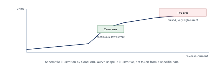
Both parts are diodes operated in reverse breakdown, both are drawn with the same symbol, and both are described in datasheets using the same three or four parameter names. The difference is what you are asking them to do all day: regulate a voltage continuously, or absorb a rare event and get out of the way.
Last updated:
Why beginners confuse them
The confusion is structural rather than careless. A Zener and a TVS use the same physical mechanism — controlled reverse breakdown — so any explanation that stops at the mechanism describes both of them. The two parts only separate when you ask how often they are expected to conduct, for how long, and with how much energy.
The analogy that resolves it is a pressure relief valve versus a pressure regulator. A regulator sits in the line and holds the output at a set pressure continuously, adjusting as flow changes. A relief valve stays shut and opens only when pressure exceeds a safe limit, then closes again. Both are valves, both are set to a number, and fitting the wrong one is immediately obvious in operation — which is exactly the situation with these two diodes.
What each was designed for
A Zener diode is designed to conduct continuously in breakdown while holding a reasonably stable voltage, and its datasheet is written around that steady state: the nominal voltage, the tolerance on that voltage, the test current, the dynamic resistance and the continuous power the package can dissipate. It is a reference and a regulator, and its performance is judged by how little the voltage moves as current and temperature change.
A TVS diode is designed to be off, and to conduct only during a transient, and its datasheet is written around that event: the standoff voltage it must not conduct below, the breakdown range, the clamping voltage at a high pulse current, the peak pulse power for a defined waveform, and often the capacitance. It is a clamp, and its performance is judged by how quickly it responds and how much energy it survives.
Speed of response, in everyday terms
Both devices begin to conduct as the voltage crosses their breakdown point, so the honest statement is that neither is instantaneous. The practical difference lies in how the part is built and specified. A TVS is optimised to present a low impedance within the timeframe of an event that lasts nanoseconds to microseconds, and its datasheet is written to let a designer check that. A Zener is optimised for a stable steady state, and its datasheet does not describe nanosecond behaviour because that is not its job.
The consequence is easy to state and easy to forget: a Zener protecting a fast transient is not a slower version of a TVS, it is an unspecified device in that role. It may work on a bench and fail in a product, because the event you are guarding against is defined by a standard that includes a rise time the part was never characterised for.
A three-scenario chooser
Most beginner decisions resolve into three cases, and the choice follows from the duty cycle.
You are holding a voltage during normal operation. A shunt regulator for a small reference rail, a clamp that has to sit at a defined level while the circuit runs, a bias network. This is a Zener’s job, and the parameters that matter are tolerance, test current and continuous power.
You are guarding a port or a node against an event that should never happen. A connector a user might touch, a cable that might collect a surge, an inductive load that might release its energy into the rail. This is a TVS’s job, and the parameters that matter are standoff voltage, clamping voltage and pulse capability.
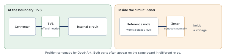
You are doing both, at different points on the same board. That is normal, and it is why both parts often appear in one design — a Zener holding a reference, a TVS guarding the input. They are not competing for the same position.
What happens when you swap them
Put a TVS where a Zener belongs and the circuit starts to drift. The reference moves with current and temperature more than the design assumed, and because the TVS is often specified with a wide breakdown range, the nominal output may be well outside what the circuit needs. The board may still function, which is worse than failing, because the error shows up as an unexplained measurement problem rather than a fault.
Put a Zener where a TVS belongs and the failure is deferred. The part may survive the surge you test with and fail the standard you did not, or it may degrade quietly until a later event finishes it. Because a failed clamp usually shorts, the symptom appears as a dead rail rather than as damage to the circuit it was supposed to protect — and the protection part itself becomes the fault to find.
Designers who have been through a few projects tend to keep four numbers for each protected node in a spreadsheet: the normal voltage, the maximum tolerable voltage, the energy of the expected event, and the capacitance budget of the line. With those four numbers written down, comparing two candidate parts becomes a mechanical exercise rather than a judgement call — and if any one of the four is unknown, the selection is a guess wearing a datasheet.
Summary table
| If your requirement is… | Choose | Because |
|---|---|---|
| Hold a reference voltage while the circuit runs | Zener | Its datasheet is written around continuous conduction and tolerance |
| Survive a defined transient at a connector | TVS | Its datasheet is written around pulse power and clamping |
| Protect a fast data line | ESD-optimised TVS | Low capacitance matters as much as clamping |
| Clamp a gate or a comparator input continuously | Zener | The duty cycle is continuous, not transient |
| Absorb energy from an inductive load | TVS or a dedicated clamp, not a Zener | The event is energetic and repeated, which is a pulse specification |
Use the simple scenarios before reading the rating calculation
TVS and Zener devices can both use reverse breakdown, but their intended duty and specified limits differ. Start with the circuit task: a steady reference or regulation function, or a transient-clamping event. Read the exact datasheet rather than identifying the device from a similar-looking symbol.
FAQ
What are the disadvantages of using a Zener diode?
For regulation, the main drawbacks are loose tolerance, a voltage that drifts with temperature and with current, and the fact that it must be biased continuously — which means it wastes current even when the load needs none. For transient protection, the disadvantage is fundamental: the part is not specified for pulsed energy, so its behaviour in that role is unknown rather than merely mediocre.
When to use a TVS diode?
When the event is occasional and fast, and when keeping the circuit running matters. Typical situations are a connector a person can touch, a cable that runs outside an enclosure, a vehicle harness, a mains input, and any node where an inductive load can release stored energy. If instead your circuit needs a stable voltage continuously, that is a regulator’s job, and a Zener or an active regulator belongs there.
Is a TVS diode a Schottky diode?
No, though both are fast. A Schottky diode is a forward-conduction device used for rectification and low forward drop; a TVS is a reverse-breakdown device used for clamping. They can appear in the same circuit for different reasons — a Schottky rectifying in the forward direction, a TVS waiting in the reverse direction — and neither substitutes for the other. Schottky diodes do also break down in reverse, which is why the confusion exists, but that breakdown is not what they are specified for.
Can I use a normal diode instead of a Zener diode?
Only for a narrow purpose, such as blocking reverse current, where you want the diode’s ordinary forward behaviour. A normal rectifier is not a voltage reference and is not specified for controlled breakdown, so it cannot hold a level the way a Zener does. If the job is holding a voltage, the part has to be specified for that job.
How do I know which one a circuit needs?
Ask how often the part is expected to conduct. Continuously means a regulator or reference, and a Zener is a simple version of that. Almost never, and only during an event, means a clamp, which is a TVS. If both descriptions apply to the same board, that is normal — they belong at different points, as the figure above shows.
What to do next
Pick the node you are worried about and write down its normal voltage, its maximum tolerable voltage and how often an event is expected. Those three lines separate the two device classes for you, and they are also the first three things a supplier will ask. The definitions used in the protection decision are set out in the TVS selection guide, and the wider family picture is in the product family learning centre.
Describe the node, its normal voltage and the event you expect, and Good-Ark can tell you whether the answer is a clamp, a reference or both.
Email sales@goodark.com, or see the families at the TVS portfolio page.
This article is published by Good-Ark, a manufacturer of both device classes discussed. It describes the general division of labour between them; specific ratings and tolerances come from the current official datasheet of the part you are considering.
Continue through this engineering topic
For the complete selection, design, verification, and troubleshooting path, explore the TVS ESD and Surge Protection Hub.
Recommended
 Why Do Diodes Get Hot? Conduction and Switching Losses ExplainedInfoStandard, Fast Recovery, and Schottky Diodes: What’s the Difference?Info
 What Is a Fast Recovery Diode? Understanding “Fast Recovery”Info
 What Is a Diode? A Beginner’s Guide to How It WorksInfo
 Automotive Semiconductor Report 2026: Chips Per Car Keep RisingKnowledge