Diode Anode and Cathode: How to Tell Which End Is Which Every Time
Diode anode and cathode: the band marks the cathode, not the anode. How to read through-hole, SMD and bridge markings, and confirm them with a meter.
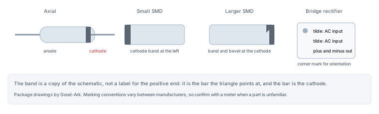
Almost every beginner destroys something by fitting a diode the wrong way round, and the reason is nearly always the same: the band on the package marks the cathode, and most people assume the banded end is the positive one. Getting this single convention straight prevents the majority of early failures in this device class.
Why polarity mistakes kill circuits
A diode fitted backwards does not simply work less well; it inverts its function. Where the circuit expected current to flow, it is blocked, so the supply produces no output. Where the circuit expected blocking, it conducts, so the diode becomes a near short across a supply or a capacitor and something else in the path takes the current until it fails.
The damage is usually to the diode itself or to whatever feeds it, and it can be quick. A reversed rectifier in a power supply can fail the diode, blow the fuse and, in a design with no protection at the input, stress the smoothing capacitor before anybody notices the smell. That is why the polarity check is worth doing twice: once when you read the part and once when you fit it.
The band, the stripe and the flat edge
On an axial through-hole diode — the small cylinder with a wire at each end — the cathode is marked with a painted or moulded band near one end. That band is the most reliable convention in the whole component family, and it corresponds to the bar in the schematic symbol. The triangle in the symbol is the anode, the bar is the cathode, and the band on the part is the bar drawn on the package.
Some packages add a second clue. Plastic-bodied types sometimes have a flattened edge on the cathode side, and glass-bodied types can carry a coloured band whose appearance changes under different lighting. Where two markings appear to disagree, trust the band and confirm with a meter rather than resolving the conflict from a reflection.
| Package family | How the cathode is marked | What confuses people |
|---|---|---|
| Axial through-hole, glass or plastic body | A band near one end | Assuming the band marks the positive end |
| Small surface-mount, such as SOD-123 | A thin band across the body at one end | The band is faint, or partly worn away |
| Larger surface-mount, such as SMA, SMB, SMC | A band or a chamfered edge at one end | Two marks that appear to point different ways |
| MELF and cylindrical surface-mount | A band, often combined with a colour code | Reading the band as a value rather than as polarity |
| Bridge rectifier package | Terminal symbols: inputs marked as alternating current, outputs marked plus and minus | Assuming the geometry is symmetrical because the terminals look evenly spaced |
SMD marking conventions
Surface-mount diodes use the same idea in less space. The cathode is normally marked with a band at one end of the body, sometimes supplemented by a chamfer or a notch. On very small packages the band is a narrow strip that is easy to miss, and on some types it is a printed line rather than a moulded feature.
Two complications are worth knowing. Some manufacturers have used the opposite convention on particular product families for historical or process reasons, and state it in the datasheet rather than on the part. And the cathode band on a two-terminal surface-mount diode can be confused with orientation marks used on other component types. Both problems have the same solution: check the specific part’s datasheet rather than relying on a general rule, and confirm with a meter before committing.
Bridge rectifier terminals
A bridge rectifier is four diodes in one package, so its terminals are not anodes and cathodes but a pair of alternating-current inputs and a pair of direct-current outputs. The inputs are usually marked with a tilde symbol and the outputs with plus and minus, and many packages add a corner mark or a bevelled edge that identifies one terminal for orientation. The datasheet says which.
The practical trap is treating the package as symmetrical because the four terminals look evenly spaced. They are not interchangeable: connecting a bridge the wrong way round usually places two of its internal diodes directly across the supply, which produces a short and a fast failure. Where a board has a square pad for one pin, that pad is the orientation reference and the silkscreen should agree with it.
How to confirm with a multimeter
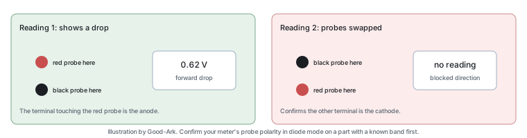
If the marking is missing, worn or unfamiliar, the meter settles it. Set the meter to diode mode, measure across the two terminals, then swap the probes and measure again. One direction shows a forward voltage drop — typically a few hundred millivolts for a Schottky and around 0.6 to 0.7 volts for an ordinary silicon diode — and the other shows no conduction.
The direction that conducts tells you which probe is on the anode. On most meters in diode mode the red probe is internally positive, so the terminal touching the red probe when the display shows a forward drop is the anode, and the other is the cathode. Test that assumption on a diode with a known band before relying on it, because a few meters reverse the convention in this mode.
Cases where markings mislead you
Four situations cause trouble even for careful people. A diode removed from a board may carry marks from the extraction process, and a cleaned or scorched body can lose its band entirely. A part from an unknown source may not follow the convention of the manufacturer whose code it imitates, which is one reason re-marked parts are a problem for repair work. A package can carry two marks, one for polarity and one for a grade or a factory, and they can point in opposite directions. And a bridge or multi-diode package can carry orientation marks that refer to a corner rather than to a terminal.
In each case the answer is the same: do not resolve the ambiguity by reasoning from the marking alone. Measure, or look up the specific part number, and if neither is possible, treat the part as unidentified rather than guessing. The article on reading the printed codes on a part covers the lookup side of that problem.
If you want to check a marking convention against an external reference, the symbols and behaviour are described under diodes, the three-terminal relative under bridge rectifiers, and the measuring technique in our guide to the multimeter. Component test methods come from JEDEC, soldering and assembly expectations from IPC, the documentation duties that make a datasheet revision traceable from ISO, the substance restrictions that appear on component declarations from the EU RoHS Directive, and industry-level material from the Semiconductor Industry Association. Device and assembly background is published by NIST.
A printable identification sheet
The routine that works, in five steps.
- Look for a band, stripe, chamfer or corner mark, and note which terminal it is nearest.
- Find the same part number in a datasheet and check the marking specification rather than a photograph.
- If the part number is unknown, measure in both directions with a diode test.
- Confirm your meter’s probe convention on a part with a known band.
- Before soldering, check the board silkscreen: a bar on the silkscreen marks the cathode and should agree with the part’s band.
Those five steps take under a minute and have prevented more dead components than any other beginner habit. If you are designing the board rather than repairing one, the equivalent discipline is making sure the silkscreen marking is unambiguous at a glance and matches the footprint you assigned in the library.
FAQ
Which side of the diode is positive?
The anode is the positive side in the sense that matters: under forward conduction the anode sits at a higher potential than the cathode, and current enters there. The band on the package marks the cathode, so the banded end is the one connected toward the more negative side of the circuit in a forward-biased arrangement. A diode is not a voltage source, so calling either end positive describes a circuit condition rather than the part on its own.
Is a cathode positive or negative?
The cathode is the terminal from which conventional current leaves a forward-conducting diode, which means it sits at the lower potential in that condition — so it is the negative terminal in the everyday sense. The confusion arises because the cathode is the marked end, and people expect the marked end of a component to be positive. Separating the two ideas helps: the mark tells you which terminal it is, and the circuit tells you what potential it sits at.
How can I tell if a terminal is the anode or the cathode?
Three routes, in order of reliability. The datasheet’s marking specification is definitive for a known part. A diode-mode measurement is definitive for an unknown part, provided you have confirmed your meter’s probe convention. A visual band works for the common packages and fails when the marking is worn, non-standard or absent. When the visual route is ambiguous, use one of the other two rather than assuming.
How do I identify the terminals of a bridge rectifier?
By the terminal symbols rather than by position. The two alternating-current inputs are usually marked with a tilde and the direct-current outputs with plus and minus. A corner mark or a bevelled edge identifies one terminal for orientation, and the datasheet says which one. Because a wrongly connected bridge can place two of its internal diodes across the supply, the orientation check is worth doing before power is applied rather than after.
Does the band ever mark the anode?
Not on the mainstream families, where the band marks the cathode without exception. Isolated products have used other conventions, and some multi-diode packages use marks that refer to orientation rather than polarity, which is why the honest answer to this question is a datasheet check rather than a rule. For the parts you are likely to meet, band means cathode.
What to do next
Practise on three diodes you already have: find the band, measure both directions, and compare your prediction with the meter. Once the band and the symbol are linked in your head, neither will slow you down again. If you want the concept behind the symbols first, start with what a diode is.
Good-Ark can confirm the marking convention, the orientation reference and the datasheet revision for a part you are trying to identify.
Email sales@goodark.com, or start from the datasheet verification guide.
This article is published by Good-Ark, a manufacturer of diodes and other discrete devices. Marking conventions are described as general practice; the definitive source for any specific part is its current official datasheet.
Continue reading
Browse the Rectifier Packages and Circuit Design for related guides.
Recommended
 Why Do Diodes Get Hot? Conduction and Switching Losses ExplainedInfoStandard, Fast Recovery, and Schottky Diodes: What’s the Difference?Info
 What Is a Fast Recovery Diode? Understanding “Fast Recovery”Info
 What Is a Diode? A Beginner’s Guide to How It WorksInfo
 Automotive Semiconductor Report 2026: Chips Per Car Keep RisingKnowledge