What Is a Bridge Rectifier? Turning AC Into DC, Explained With Pictures
Follow the current through four diodes on each half of the AC cycle to see how a bridge rectifier turns AC into DC and what the output looks like.
Updated: October 27, 2026
A bridge rectifier is four diodes (or a packaged bridge) arranged to convert AC into a single-polarity DC rail—full-wave using both halves of the AC cycle.
Below is a practical definition, the ratings that matter, and where this part sits among related guides: Bridge rectifier guide, 400 Hz Aircraft Ac Rectification Bridge Loss Harmonics and Validation, Breadboard Bridge Rectifier Build It From Four 1n4007s and Verify.
| Question | Short answer | Watch-out |
|---|---|---|
| What it does | Full-wave AC→DC | Not a regulator |
| Key ratings | VRRM, IO, IFSM | Ignoring surge on capacitor charge |
| Package | Discrete vs molded bridge | Thermal path undersized |
| Next | Filter capacitor + load | Expecting smooth DC from bridge alone |
AC and DC in one picture
Alternating current reverses direction many times a second. In a 50 hertz supply it changes direction a hundred times, fifty in each direction. Direct current flows one way. Rectification is the process that turns the first into the second, and a bridge rectifier does it without needing a special transformer, which is why it is the standard approach.
The mental model worth holding is a set of one-way doors arranged around a loop. Current arriving from one input passes through whichever doors are open in the forward direction and exits at the same output terminal as current arriving from the other input. The input alternates; the output does not. Everything else in this article is detail on that idea.
Why flipping the negative half helps
A single diode passes only the half of the waveform that pushes current in its forward direction, so the other half is simply discarded. That circuit still works, and it is still used for small loads, but it wastes half the available energy and produces an output with long gaps between pulses.
The bridge solves this by connecting the input so that whichever half of the cycle is active, the current is routed through the output in the same direction. The negative half is not discarded; it is flipped, which is why the technique is called full-wave rectification. The practical result is that the output pulses twice as often as the input, which means the smoothing capacitor has half as long to hold the voltage up between pulses and can therefore be smaller for the same result.
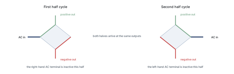
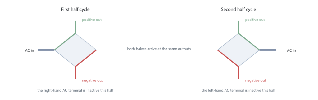
Path of current in the first half cycle
Take the first half of the cycle. Current enters through one alternating-current terminal and finds two diodes whose forward direction points the right way: one from that terminal up to the positive output, and one from the negative output up to that terminal on the return path. The current therefore leaves at the positive terminal, passes through the load, and returns at the negative terminal.
The other two diodes are reverse biased during this half, so they block. That is important for two reasons: it prevents a direct short across the input, and it means only two of the four devices are conducting at any moment. The bridge is not four diodes working together; it is two pairs taking turns.
Path in the second half cycle
Now the input reverses. Current enters through the other alternating-current terminal, and this time the roles swap: the two diodes that were blocking now conduct, and the two that were conducting now block. Crucially, the current still leaves at the positive output and returns at the negative one, because the second pair is arranged to route it the same way.
That is the trick, and it is worth pausing on: nothing switches, nothing is timed, and no control signal exists. The diodes simply respond to the voltage across them, and the geometry of the connection means the current can only ever leave in one direction.
What the output really looks like
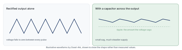
The output is not a flat line. It is a series of humps, one for each half of the input cycle, all rising from zero to a peak and back. With a 50 hertz input that means a hundred humps a second, and the voltage falls between them. This is often described as pulsating direct current, and the description is accurate: the current always flows the same way, but its magnitude is not constant.
What the load does with those pulses depends on the load. A resistive load simply sees a varying voltage. Most electronic circuits cannot tolerate that, which is why a capacitor is added next.
| Arrangement | Pulses per input cycle | Voltage lost in the path | Transformer needed |
|---|---|---|---|
| Half-wave, one diode | One | About 0.7 V | Any ordinary secondary |
| Centre tap, two diodes | Two | About 0.7 V | Centre-tapped secondary |
| Bridge, four diodes | Two | About 1.4 V | Any ordinary secondary |
Read the last two rows together and the trade becomes visible: the bridge gives the smoothness of full-wave rectification without the transformer constraint, and pays for it with a second diode drop in the path. That single comparison explains why bridges dominate mains-powered equipment and why low-voltage designs sometimes avoid them.
Adding a capacitor, simply
A capacitor connected across the output charges as the pulse rises and discharges into the load as the pulse falls. The result is a voltage that sags slightly rather than dropping to zero, and the size of the sag depends on the capacitance, the load current and how long the gap between pulses lasts. That is why a full-wave rectifier needs less capacitance than a half-wave one for the same performance: its gaps are half as long.
Two practical consequences follow. First, the capacitor charges through the diodes in short, high-current bursts rather than a smooth draw, so the diodes see current peaks well above the average. That matters for both the bridge’s thermal design and its surge rating, and it is a detail that catches out people who size a bridge on average current alone.
Two more external references are worth having for the design side. The smoothing capacitor that follows the bridge is described under filter capacitors, and the transformer arrangement that the bridge makes unnecessary under centre tap. Device test methods come from JEDEC and assembly expectations from IPC, with sector-level reporting from the Semiconductor Industry Association. Device and assembly background is published by ISO, NIST and IEC.
Two diodes versus four
A centre-tapped transformer with two diodes achieves full-wave rectification as well, and it has one real advantage: only one diode is in the conducting path at any moment, so the voltage lost is roughly half that of a bridge. The price is the transformer, which needs a centre tap and uses its copper less efficiently because each half of the winding conducts only half the time.
The bridge avoids the special transformer, which matters commercially, and pays with an extra diode drop in the path. Two diodes conducting in series at roughly 0.7 volts each means about 1.4 volts lost, which is negligible in a 300 volt circuit and significant in a 5 volt one. That trade — and the situations where it flips — is the subject of our article on why a bridge uses four diodes.
Common questions
The two questions that come up most often are about naming and about failure. On naming: the arrangement is also called a full-wave bridge rectifier, a bridge module when it is packaged for chassis mounting, and in older texts a Graetz circuit or Graetz bridge, after the engineer who popularised it. The names describe the same thing.
On failure: because the part is small and sits at the input, it works hard, and the two most common causes of failure are inrush current at switch-on and overheating from a marginal thermal design. A shorted bridge usually announces itself with a blown fuse, while an open one produces excess ripple or a lower output. Our article on the bridge rectifier package and its ratings covers the package side, and related reading on our own site covers diode bridge, rectifiers and ripple.
Read the marked terminals before choosing a replacement
The current paths explain the bridge circuit. For an actual package, use its two AC terminals and marked positive and negative terminals, then compare voltage, current, surge, and mounting conditions. The bridge family and package guide covers those engineering checks.
Field checklist
- Size VRRM from peak AC plus margin, not RMS alone.
- Check inrush into empty capacitors (IFSM).
- Plan heatsinking for average current at your ambient.
FAQ
Half-wave vs bridge?
Half-wave uses one diode and wastes a half-cycle; a bridge uses both halves and needs a center tap less often.
Why is the DC still rippled?
The bridge only rectifies; capacitors and/or regulators smooth and regulate.
Can I use four discrete diodes?
Yes if ratings and layout match; molded bridges simplify assembly.
Related guide?
Continue through this engineering topic
- Bridge rectifier guide
- 400 Hz Aircraft Ac Rectification Bridge Loss Harmonics and Validation
- Breadboard Bridge Rectifier Build It From Four 1n4007s and Verify
- Bridge Failure Signatures in Power Supplies Burn Patterns Shorts and
- Bridge Rectifier Failures in Motor Drives Field Patterns and Fixes
- Bridge Rectifier Sizing for Dc Motor Drives Stall Current Lr
Topic hub: Bridge rectifier guide — related selection guides and application notes in this cluster.
Explore the related topic guides
Continue with the related selection, design and verification guides: