SiC in Solar Inverters: Why a Few Percent of Efficiency Matters
SiC in solar inverters: where the losses go, why silicon carbide reduces them, and what that means over the life of a home or utility installation.
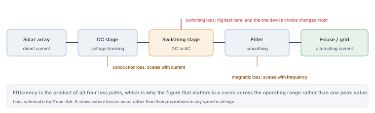
An inverter is the only part of a home solar system that works every day the sun rises, and it is usually the first major component to be replaced. Its efficiency is therefore not a laboratory number: every per cent is energy that either reaches your house or becomes heat inside a box mounted on a wall.
Last updated:
What an inverter does
Solar panels produce direct current at a voltage that varies with sunlight and temperature. Houses and grids run on alternating current at a fixed frequency and voltage. The inverter sits between the two and performs three jobs: it tracks the panel’s best operating point as conditions change, it converts direct current to alternating current, and it synchronises that output with the grid so it can be fed in safely.
The middle job is where the switching devices sit. Conversion happens by chopping the direct current into a pulse pattern and filtering it into a sine wave, and every chop consumes a small amount of energy. The analogy that fits is a water wheel that has to be turned on and off thousands of times a second: the faster and more cleanly it turns, the less water is spilled.
Where energy is lost
Losses in an inverter come from four places. Conduction losses occur whenever current flows through a device that has resistance. Switching losses occur each time a device changes state. Magnetic losses occur in the inductors and transformer that shape the output. And control and auxiliary losses keep the electronics alive even at low output.
The proportions change with load. At low output, fixed losses such as control power dominate, which is why an inverter’s efficiency curve is usually lowest near the bottom of its range. Around the middle of the range, conduction and switching losses dominate, and that is where the choice of switching device matters most. This is why the efficiency figure that counts is not a single peak number but the curve across the range the system actually operates in.
Why fewer losses mean smaller boxes
Heat is what shapes an inverter’s physical size. A unit that wastes less energy needs a smaller heatsink, and because silicon carbide switches faster without extra loss, the design can also raise its switching frequency. Higher frequency shrinks the inductors and transformer, which are usually the bulkiest components in the unit.
That combination is why wide-bandgap devices have moved quickly into this application. The gain is not only the efficiency percentage; it is the ability to build a lighter unit that hangs on a wall, survives a hot summer and costs less to ship and install.
Heat and lifetime in a sunny climate
An inverter outdoors or on a garage wall spends its life at temperatures well above room conditions, and its semiconductor devices degrade faster when they run hot. Two effects make the thermal margin matter more than the efficiency number suggests. First, a hotter device has higher conduction loss, so heat and loss reinforce each other. Second, thermal cycling — the daily expansion and contraction as the sun rises and sets — is a fatigue mechanism that eventually finds weak points in solder joints and bond wires.
Reducing the loss improves both. Lower loss means lower junction temperature, which slows the degradation, and it also flattens the daily temperature swing, which reduces the mechanical fatigue. For a device expected to run for fifteen or twenty years, that is a reliability argument rather than an efficiency argument, and it is usually worth more than the energy saved.
What silicon carbide changes inside
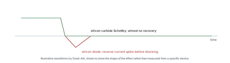
Two positions in an inverter benefit from silicon carbide. The first is the switching stage, where the devices chop the direct current into an alternating pattern; silicon carbide MOSFETs reduce both conduction and switching loss, and they tolerate a higher switching frequency. The second is any position where a diode has to stop conducting quickly, because a silicon carbide Schottky diode has almost no reverse recovery — the brief burst of current that a conventional diode produces when it turns off.
That second point is easy to underestimate. Reverse recovery not only wastes energy; it also creates a current spike that stresses the device beside it and radiates noise. Removing it simplifies the design of the rest of the circuit, which is one reason a silicon carbide upgrade often ends up changing more than the two devices the designer originally intended.
There is also a maintenance argument that homeowners rarely hear. An inverter is normally the first major component to be replaced in a solar system, and the cost of that replacement includes labour and scaffolding as well as the unit. A design that runs cooler and weighs less is easier to service, which is a real part of its lifetime cost even though it never appears on a datasheet.
What it means for a home system
For a homeowner, the honest expectation is modest. A more efficient inverter converts a slightly larger share of panel output into usable electricity, and because it runs every day, the kilowatt-hours accumulate over years. But efficiency claims are easily overstated: a difference of one or two percentage points is real and worth having, and it is not a reason to replace a working inverter.
The more tangible benefits are reliability and physical practicalities. A lighter unit is easier to mount, a cooler one lasts longer in a hot climate, and a smaller one may fit where a larger unit would not. If you are choosing between two inverters, the warranty terms and the servicing network will usually matter more to your total cost than the efficiency difference.
| Claim | Realistic assessment |
|---|---|
| Higher conversion efficiency | Yes, typically by a small number of percentage points, and it accumulates because the unit runs daily |
| Smaller, lighter unit | Yes, and this is often the most noticeable benefit at installation |
| Better performance in high heat | Yes, because less loss means a lower operating temperature and more margin on hot days |
| Longer life | Plausible through lower thermal stress, but the warranty terms are what protect you, not the technology claim |
| Dramatically more annual yield | No. The improvement is incremental, and panel orientation, shading and location dominate the annual figure |
What still limits the gain
Three things cap what an inverter can deliver. The panels themselves set how much energy is available, and no converter can exceed that. The inverter’s own fixed losses — control electronics, displays, communications — do not disappear when the switching devices improve, and they dominate at low light. And the grid interface imposes limits on power quality and on how much the unit may export, which is a regulatory constraint rather than an engineering one.
The practical consequence is that silicon carbide raises the ceiling slightly rather than resetting it. In a system with shading or a poorly oriented array, fixing the roof-side problem will always beat upgrading the electronics.
External references are useful when checking claims: the device class that does the switching is described under power MOSFETs, the material under silicon carbide, and the device that benefits most from the material under Schottky diodes. Grid-connection and safety expectations come from the International Electrotechnical Commission, energy-efficiency and solar programmes from the US Department of Energy, and sector-level reporting from the Semiconductor Industry Association. Wide bandgap and sector background is published by JEDEC, NIST and ISO.
FAQ
What is the SIC code for solar installation?
This question is about the Standard Industrial Classification, a system for categorising business activity, and it is an acronym collision with silicon carbide. In the older SIC system, solar-related installation work generally falls under electrical contracting categories, and the newer NAICS system has separate codes for solar electric power generation and for solar installation contracting. Because classification systems differ by country and are updated periodically, check the current code list for the country your business operates in rather than relying on a general answer.
What are the three main types of solar inverters?
The conventional split is string inverters, central inverters and microinverters. A string inverter serves a whole array wired in series and is the common choice for homes. A central inverter serves a large commercial or utility installation, handling high power in one place. A microinverter is fitted at each panel, converting at the source, which helps when panels are shaded or face different directions. A fourth category, the hybrid inverter, adds battery management to the same box.
Should you leave your inverter on all the time?
It is designed to run whenever the array is producing, and it goes into a low-power sleep at night when there is nothing to convert. There is no benefit to switching it off each evening, and doing so would interrupt monitoring and any automatic grid-support functions. What matters is that it can ventilate: a unit in an enclosed cupboard runs hotter and loses more efficiency than the same unit on an open wall.
What is the difference between a CSI and a VSI inverter?
CSI stands for current-source inverter and VSI for voltage-source inverter, and the distinction is about what the DC side presents to the switching stage. A voltage-source inverter holds a stiff DC voltage, usually across a large capacitor, and the switching stage applies that voltage to the output in pulses. A current-source inverter works with a controlled DC current, typically through a large inductor, and switches that current between output phases. Most modern grid-tied solar inverters are voltage-source designs, but the current-source topology still appears in high-power and drive applications.
Do I need a wide-bandgap inverter to get good performance?
No. A well-designed inverter using conventional silicon devices can achieve excellent efficiency, and the difference between a good silicon design and an average wide-bandgap one is larger than the difference between the technologies. What the material changes is how much thermal margin the designer has, which affects the achievable size and the operating temperature rather than whether the product is good.
What to do next
If you are specifying an inverter, ask for the efficiency curve rather than a single peak figure, and check the value across the output range your array will actually produce. If you are designing one, the switching device choice is only one of four loss paths, and the filters and magnetics usually decide how much of the switching gain survives. The device-level comparison is in our guide to what to check in high-voltage SiC MOSFETs.
Tell Good-Ark the DC voltage range, the switching frequency and the thermal budget, and we can point to the SiC diode and MOSFET families that fit, with the documents needed to qualify them.
Email sales@goodark.com, or start from the SiC portfolio page.
This article is published by Good-Ark, a manufacturer of silicon carbide devices used in power conversion. It describes the general role of the material in inverter design rather than the performance of any specific product.
Continue through this engineering topic
For the complete selection, design, verification, and troubleshooting path, explore the Solar and PV Electronics Hub.
- Practical guide: Power MOSFETs for SMPS, PV Inverters and Automotive Circuits
- Practical guide: How Do Solar Garden Lights Work? (And Why So Many Die)
- Practical guide: How a Solar Module Gets Qualified: Where the Bypass Diode Is Tested and What Failures to Expect
- Ask Good-Ark technical support about this application
Recommended
 Why Do Diodes Get Hot? Conduction and Switching Losses ExplainedInfoStandard, Fast Recovery, and Schottky Diodes: What’s the Difference?Info
 What Is a Fast Recovery Diode? Understanding “Fast Recovery”Info
 What Is a Diode? A Beginner’s Guide to How It WorksInfo
 Automotive Semiconductor Report 2026: Chips Per Car Keep RisingKnowledge