Choosing a MOSFET for Your First Project: A Beginner Checklist
Choosing a MOSFET for beginners: four questions answer most first projects, covering blocking voltage, heat tolerance, gate voltage and soldering.
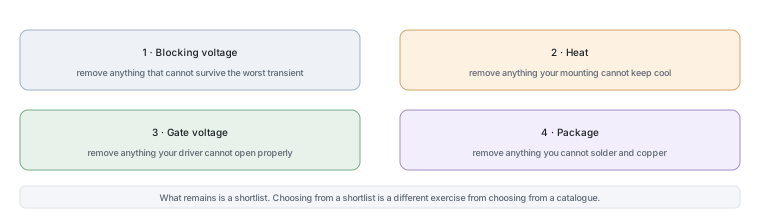
Four questions answer most first-project selections, and three of them are about the circuit rather than the part. Answer those before opening a catalogue and the choice usually narrows to a handful of candidates that are all capable of doing the job.
Four questions before you open a catalogue
What voltage must the device block, including the worst transient the circuit can produce? How much current will it carry, and how much heat can your mounting actually shed? What gate voltage will your circuit provide? And what package can you reliably solder and give copper to? Those four answers replace almost everything a beginner tries to hold in their head at once.
The reason to start here rather than with part numbers is that requirements survive while availability changes. A design chosen from requirements can be re-sourced when a part goes out of stock; a design chosen from a part number has to be redone.
Voltage: leave room for spikes
The blocking voltage must exceed the highest voltage the device will see, not the nominal supply. In a switching circuit that means adding margin for the voltage spike that appears when current through an inductor is interrupted, which can be several times the supply voltage. In a battery circuit it means allowing for a fully charged pack plus any series transient. In a motor circuit it means allowing for the voltage generated while the motor is coasting.
A common beginner mistake is to specify the blocking voltage from the supply alone. A twelve volt supply with no margin is not a twelve volt requirement; it is a requirement that might be twenty or thirty volts once switching and inductance are accounted. Choosing a part with inadequate blocking headroom produces a device that eventually fails in avalanche, usually at the moment of switch-off, and the failure is often blamed on the part rather than the specification.
Current: think about heat, not the label
The current rating on a datasheet is quoted at a case temperature, and the part can only reach that figure if your mounting can keep the case there. In a sealed enclosure with no airflow, a small surface-mount part may reach only a fraction of its headline current before overheating, which is why the honest way to select is to work out the heat rather than to compare current numbers.
The arithmetic is short. Estimate the conduction loss from the hot on-resistance and your current, estimate or look up the thermal resistance for your actual mounting, multiply to get the temperature rise, and add the ambient inside the box. If the result is comfortably below the device’s limit, the part is suitable; if not, the fix is a lower resistance part, more copper, or both. Our article on why MOSFETs get hot walks through the calculation.
Logic level or not
A device specified for logic-level drive reaches its rated on-resistance at a gate voltage a microcontroller pin can supply, typically a few volts. A device specified for a higher gate voltage will still conduct at that level, which is what makes the mistake so easy to miss: the circuit works, but the channel is only partly open and the effective resistance may be several times what the datasheet headline suggests.
The check is to look for the on-resistance figure at the gate voltage you will actually use. Datasheets usually plot more than one curve for this reason, and the one that applies is the one matching your driver rather than the one with the smallest number. Our article on driving loads directly from logic pins covers the detail.
Package and how you will solder it
The package decides three things at once: whether it fits your board, whether you can attach it, and how well it sheds heat. A large tabbed part mounted on copper cools well and takes space; a leadless part with a pad underneath cools well only if your board has the copper and your process can solder a pad you cannot reach with an iron.
For a first project the practical choice is usually a package you can see and reach — something with visible leads — because the thermal performance is easier to reason about and the assembly cannot go subtly wrong. Leadless packages are excellent once you have the process for them, and frustrating before that.
| Question | Eliminates | Symptom if you get it wrong |
|---|---|---|
| Blocking voltage with transient margin | Parts that cannot survive the circuit | Failure at switch-off, often after some time in service |
| Heat at your mounting | Parts your board cannot cool | High temperature, then a short service life |
| Gate voltage | Parts your driver cannot open | Works, but runs much hotter than expected |
| Package | Parts you cannot attach or copper | Open joints, or a part that never reaches its rating |
Three example projects, three picks
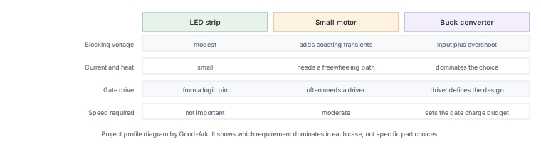
The selection logic is easier to see applied. For switching a small LED strip from a microcontroller pin, the voltage is low, the current is modest and the gate comes from a logic pin, so the requirements point to a small logic-level surface-mount device with modest current capability and no thermal design at all.
For controlling a small brushed motor from a battery pack, the voltage includes the motor’s coasting transients, the current is higher and the gate drive may need a driver rather than a bare pin. The requirements point to a mid-range device with a package that can be given copper, plus attention to the freewheeling path the motor needs.
For a buck converter, the switching frequency adds a requirement the other two did not have: the gate charge has to be small enough for the driver to switch the device quickly, and the losses now include switching as well as conduction. That makes the selection a balance rather than a threshold, and it is the case where the datasheet curves matter most.
Mistakes beginners make
Five mistakes account for most first-project problems. Specifying the blocking voltage from the nominal supply and ignoring transients. Choosing a part on its headline on-resistance without checking the gate voltage that figure was measured at. Assuming the current rating is achievable without the copper area the datasheet assumed. Omitting the gate resistor, which lets fast edges ring and can damage the driver. And forgetting the body diode, which gives current a path through the device in the off state whether you wanted one or not.
None of those requires advanced knowledge to avoid, and all of them produce failures that look like bad components rather than bad specifications. Our article on what a MOSFET is explains the mechanisms behind them.
It is also worth deciding, before you shop, whether the part is a one-off or whether you are designing something that will be built more than once. A one-off can be chosen from whatever is available and adequate. A design that will be repeated needs a part with a documented revision history and a plausible supply position, because the second build will happen after the first batch has been consumed. That difference does not change the four questions, but it changes how much weight the answers carry.
Printable checklist
- Write down the highest voltage the device will see, including switching transients.
- Write down the continuous and peak current, and the ambient inside the enclosure.
- Write down the gate voltage your circuit provides.
- Write down the packages you can solder and give copper to.
- Filter candidate parts on those four, in that order.
- For the survivors, check the on-resistance at your gate voltage, not at the headline condition.
- Estimate the junction temperature using the thermal resistance for your actual mounting.
Background written for beginners covers power MOSFET and buck converters. Device test methods come from JEDEC, thermal and assembly expectations from IPC, and sector-level context from the Semiconductor Industry Association. Device and quality background is published by ISO, NIST and IEC.
FAQ
How do I select a MOSFET for a buck converter?
The requirements are the same four, with the switching frequency added as a fifth. The blocking voltage must exceed the input voltage plus the switching overshoot. The conduction loss depends on on-resistance at your gate voltage. The switching loss depends on gate charge and how fast your driver can move it, which is why a device with excellent on-resistance and a large gate charge can be the wrong choice at high frequency. And the package has to remove both losses, not just the conduction one. Buck converters are the case where the datasheet curves matter more than the headline table.
What kills MOSFETs?
Gate overvoltage, overheating, avalanche events beyond the rating, and shoot-through in bridge circuits. Most of those are specification problems rather than faulty parts, which is why a replacement device usually fails too unless the requirement is corrected. Our article on what a MOSFET is covers the mechanisms.
What is a MOSFET, in the simplest terms?
It is a switch controlled by a voltage rather than by a finger or a current, which is why a small logic signal can turn a large load on and off. Our article on what a MOSFET is explains it in plain language with the three terminals and the two ways it produces heat.
Which type of MOSFET is better?
N-channel devices are electrically better for the same size, because their charge carriers move more readily and their on-resistance is lower. P-channel parts are convenient for high-side switching because they can be driven from the supply directly. The choice is a wiring decision rather than a quality judgement, and our article on n-channel and p-channel devices covers it.
Is it safe to use a much higher voltage rating than I need?
Safe, certainly, but not necessarily better. Raising the blocking voltage usually raises the on-resistance for the same die area, because the device needs a thicker region to withstand the higher field. An over-specified part therefore runs hotter at the same current and costs more. Choose the voltage class that covers your requirement with sensible margin rather than the largest device available.
What to do next
Write the four answers down for your project before you look at any part, and keep the note. It becomes the specification you check a substitute against in two years’ time, when the original device is no longer available and you cannot remember why it was chosen. The thermal side of the checklist is covered in more depth in our article on why MOSFETs get hot.
Tell Good-Ark the blocking voltage, the current, the gate voltage and the package you can use, and we can point to the family and rating class that fit with margin.
Email sales@goodark.com, or start from the product family learning centre.
This article is published by Good-Ark, a manufacturer of MOSFETs and other discrete devices. It describes a selection method rather than specific parts; ratings, gate requirements and thermal data belong to the current official datasheet.
Recommended
 Why Do Diodes Get Hot? Conduction and Switching Losses ExplainedInfoStandard, Fast Recovery, and Schottky Diodes: What’s the Difference?Info
 What Is a Fast Recovery Diode? Understanding “Fast Recovery”Info
 What Is a Diode? A Beginner’s Guide to How It WorksInfo
 Automotive Semiconductor Report 2026: Chips Per Car Keep RisingKnowledge