Thyristor vs Triac: AC Control Devices Compared for Beginners
Compare SCR and TRIAC operation for AC control: current direction, gate triggering, latching, holding, commutation and conditions needed for device selection.
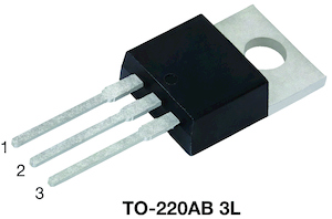
A low-power AC load flickers after a controller replaces a larger lamp. The switch still has ample headline current capacity, and the gate pulse still appears at the expected time. The missing check may be whether the new load current rises enough to latch the device and remains high enough to hold it on.
This is a hypothetical diagnostic starting point, not a reported customer failure. For a buyer comparing alternative parts or a learner reading a schematic, current rating is only one condition. The choice begins with current direction and ends with a supported trigger, commutation, and thermal envelope.
Thyristor vs triac: what is the useful distinction?
A TRIAC is itself a thyristor, so the common comparison usually means SCR versus TRIAC. A conventional SCR conducts main current in one direction after triggering; a TRIAC can control either AC polarity. Both latch under suitable conditions and normally turn off through current commutation, rather than simply when their gate drive disappears.
Start with the current path and the meaning of the names
Thyristor names a device family. SCR, or silicon controlled rectifier, refers to a particular controlled, unidirectional main-current device. TRIAC identifies a bidirectional AC control device. When a seller uses thyristor as shorthand for SCR, confirm the exact part rather than treating the two terms as a complete specification.
Littelfuse’s thyristor fundamentals note places these devices in the same family. On the schematic, locate an SCR’s anode, cathode, and gate, or a TRIAC’s main terminals and gate. Terminal names and package pin positions must come from the selected datasheet.
A single conventional SCR in series with an AC load permits controlled current in its forward direction, not symmetrical control of both half-cycles. Two appropriately driven inverse-parallel SCRs can provide bidirectional control. A TRIAC can perform a bidirectional main-current function in one device, but it is not an exact replacement for two arbitrary SCRs under every commutation condition.
Neither device should be selected by analogy with an ordinary diode alone. The standard versus fast-recovery rectifier comparison concerns uncontrolled rectification. Adding a gate and latching behavior changes how a controlled power path starts and stops.
Separate gate triggering, latching, and holding
Gate trigger current, IGT, concerns initiating conduction under specified conditions. Latching current, IL, concerns establishing enough main current for conduction to remain after the triggering signal is removed. Holding current, IH, concerns the minimum main current needed to sustain the already established conducting state under its specified conditions.
These three currents belong to different circuit questions. A drive that satisfies a gate-current entry can still fail if the gate pulse ends before main current has risen enough. A load can also stop conducting later when its current falls below the holding requirement. Temperature, waveform, and the selected device’s operating mode matter.
For a hypothetical check, suppose a candidate’s applicable maximum latching-current limit is 30 mA, while a load reaches only 20 mA by the end of the planned gate pulse. That information does not support guaranteed latching. A 4 A continuous-current headline does not fix the mismatch. Do not assign these illustrative numbers to a real part without its datasheet conditions.
Use ST AN303 for latching-current behavior and ST AN302 for holding-current behavior as separate references. Increasing pulse duration may help a slowly rising load current, but requires checks on gate limits and the intended control strategy.
Compare the functions before comparing order codes
| Question | Conventional SCR | TRIAC |
|---|---|---|
| Main current direction | Unidirectional forward conduction | Conduction in either polarity when properly triggered |
| Main terminals | Anode and cathode | MT1/MT2 or manufacturer-equivalent names |
| Gate reference | Cathode | Specified main reference terminal, usually MT1/A1 |
| Trigger requirements | Positive gate triggering for the conventional device | Permitted quadrants and their specified currents |
| Turn-off | Current commutation and adequate recovery conditions | Current commutation plus applicable commutating limits |
| Bidirectional control implementation | May require multiple devices and drives | One main device, subject to load and quadrant suitability |
| Common acceptance mistake | Assuming removal of gate drive interrupts DC | Assuming all quadrants and both terminals are interchangeable |
Do not turn this table into a universal product ranking. The required voltage, current waveform, cooling, control supply, and load type can favor different arrangements. Part availability or a familiar package cannot resolve missing electrical conditions.
Check AC timing and the load before choosing the device
For an ideal resistive AC load, current follows voltage, so natural current zero occurs with voltage zero. For an inductive load, current can lag voltage. A TRIAC can therefore encounter a significant reapplied voltage as its current commutates. Turn-off suitability needs the actual load and the relevant commutating dI/dt and dV/dt conditions.
In DC operation, the source does not supply a natural periodic current zero. A conventional SCR or TRIAC can remain latched after gate drive stops if the main current remains sufficient. The circuit must provide the required commutation or interruption. These devices are not gate-controlled turn-off switches in the ordinary MOSFET sense.
AC timing terminology also matters. At 50 Hz a half-cycle lasts 10 ms; at 60 Hz it lasts about 8.33 ms. A 90-degree firing delay from voltage zero is therefore 5 ms or about 4.17 ms, respectively. These are ideal timing relationships, not suggested gate-pulse widths or guarantees of delivered power for an arbitrary load.
With a phase-controlled resistive load, delaying turn-on changes the conducted portion of each half-cycle. Inductive loads, electronic lamp drivers, and motors can respond differently. A device that works with a heater may not produce acceptable dimming or motor behavior merely because the RMS load current appears similar.
Verify gate quadrants and transient protection together
TRIAC quadrants describe main-terminal voltage and gate-current polarity relative to the reference terminal. Not all types support all four quadrants, and trigger sensitivity can differ between the permitted ones. Check the control circuit’s source or sink capability, reference node, gate-current limit, and pulse conditions for both half-cycles.
ST AN4363 discusses device selection and triggering quadrants. A label such as logic level does not establish compatibility with every logic pin or supply polarity. The low-voltage control section may also be electrically connected to hazardous potential; its supply voltage alone does not establish isolation.
A suitable RC snubber can help manage reapplied voltage and transient behavior, but adds discharge current and component stress. Use ST AN437 for TRIAC snubber design alongside the RC and RCD snubber overview. Do not copy a capacitor and resistor from a different load without checking their function and ratings.

Measure the failure mode instead of assuming a bad part
With power isolated and stored energy handled according to the equipment procedure, verify terminal mapping, gate components, load connections, and the exact installed order code. A multimeter test can reveal some shorts but cannot qualify quadrant sensitivity, commutation, or thermal performance.
Energized mains measurements require qualified personnel and suitable instruments. Never remove an oscilloscope’s protective-earth connection to float it. Tektronix floating-measurement guidance explains why reference connections need planning before probes are attached.
Review main current and gate current on the same time base under defined conditions. Does main current reach the latching requirement before the gate pulse ends? Does conduction stop when current falls? Is there unintended retriggering during voltage recovery? Check both polarities, low and full load, startup, and relevant temperatures.
Separate these observations from heat-path checks. A device can trigger correctly while exceeding its thermal limit, or remain cool while failing to latch at low load. Keep waveform evidence and temperature evidence together without allowing either to stand in for the other.
Keep the selection record specific to the application
When checking a proposed alternative, ask what the thermal rating assumes about case temperature or heatsinking. An insulated tab, a live tab, and an added insulating pad can produce different installation requirements even when the outline looks familiar. Check the mounting method and isolation arrangement together with the thermal path. A substitution that forces a different heatsink interface can require mechanical review as well as electrical approval. Keep those changes in the comparison rather than hiding them behind a matching package name or a higher current entry.
For a sourcing or replacement decision, retain voltage ratings, repetitive RMS and average-current conditions where applicable, surge conditions, gate drive, latching and holding limits, commutation requirements, package mapping, insulation needs, and cooling assumptions. Compare the exact manufacturer part and revision, not only a generic family description.
A TVS-versus-Zener comparison can help identify a separate protection component, while silicon, SiC, and GaN technology roles provides broader context. Neither discussion replaces this controlled-switch review.
If the required action is to stop DC current directly on a logic command, revisit the switch architecture before ordering an SCR or TRIAC. If the task is AC control, establish the load, trigger quadrants, current-zero behavior, and protection network before accepting an apparently equivalent device.
FAQ
Is a TRIAC outside the thyristor family?
No. TRIACs belong to the thyristor family. In many practical comparisons, thyristor is used informally to mean an SCR, but that shorthand can hide the actual device requirement. Specify SCR or TRIAC and verify the exact part documentation. The useful comparison concerns main-current direction, gate triggering, latching, holding, commutation, and the load conditions, rather than treating the family name as a separate competing technology.
Does removing gate current turn an SCR or TRIAC off?
Not in the ordinary operation of a conventional latched device while sufficient main current continues to flow. The circuit needs current to fall below the applicable sustaining condition and must provide adequate recovery conditions. AC circuits may provide natural current commutation, while DC circuits need an appropriate interruption or commutation arrangement. Check the exact device and circuit; do not treat the gate as a MOSFET-style command to stop conduction immediately.
Can a larger current rating solve flicker at a small load?
Not necessarily. A low-current load can fail to establish latching current before the gate pulse ends, or fall below the holding requirement during operation. A larger headline RMS-current rating does not establish either condition. Check the exact latching, holding, gate, quadrant, temperature, and load-waveform requirements. Also inspect controller timing and load compatibility before assuming that a higher-current replacement will resolve the observed behavior.
Recommended
 Synchronous Rectification vs Schottky: A Beginner Decision FrameKnowledge
 Optocoupler How It Works in Isolated SMPS FeedbackKnowledge
 Soft Start and Inrush: Diode Ifsm Beside Control TricksKnowledge
 Flyback Transformer Basics for Discrete Learners (Diode-Side Focus)Knowledge
 SMPS Rectifier Diode Selection: Primary vs Secondary JobsKnowledge
 Ohm’s Law for Diode Circuits: Drop, Dissipation, Sanity ChecksKnowledge