Why Does a Bridge Rectifier Need Four Diodes?
Why does a bridge rectifier have four diodes? One wastes half the waveform, two need a special transformer, and four remove that requirement at a cost.
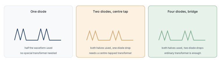
The answer is one sentence long, and the reasoning behind it is the part worth knowing: two diodes give full-wave rectification but only if the transformer has a centre tap, and four diodes achieve the same result with an ordinary transformer. The fourth pair exists to remove a requirement rather than to add a function.
Start with one diode and see what fails
A single diode in series with an alternating supply conducts on one half of the cycle and blocks the other. The output is a series of pulses with gaps between them, and no current flows at all for half the time. That is half-wave rectification, and its shortcomings are easy to state: half the available energy is unused, the output has long gaps, and the transformer’s magnetic material is idle for half of every cycle.
The gaps are the practical problem. A smoothing capacitor has to hold the load up for the whole time between pulses, which for a 50 hertz supply is a full 20 milliseconds. Keeping a useful voltage across a load for that long needs a large capacitor, and the current drawn to recharge it arrives in short, high peaks that stress the diode more than the average current suggests.
Add a second: the centre tap idea
Add a second diode and a transformer with an extra connection in the middle of its secondary winding, and something useful happens. The centre tap becomes the return path for both halves. On the first half of the cycle, current flows from one end of the winding, through the first diode and into the load. On the second half, the polarity reverses, and current flows from the other end of the winding through the second diode and into the load — in the same direction as before, because the diodes are connected with opposite orientation to the two ends.
Two pulses per cycle, one diode conducting at a time, and therefore only one diode drop in the path. That is an efficient arrangement, and it was the standard approach before packaged bridges became cheap.
Why two diodes need a special transformer
The centre tap is not a convenience; it is a requirement. The winding has to be split into two halves that are electrically identical, because each half conducts on alternate cycles and any imbalance becomes an imbalance in the output. That is a manufacturing constraint: the transformer must be wound with a tapped secondary, which is a special order compared with a plain two-terminal winding.
There is a second cost. Each half of the winding carries current only half the time, so the copper is used inefficiently and the transformer has to be larger than its average power would suggest. Both the special construction and the inefficient winding disappear if the rectification can be done without a tap, which is exactly what the four-diode arrangement achieves.
The four-diode trick that removes the transformer
Connect two diodes so that each end of an ordinary winding can supply the positive output, and two more so that each end can return the negative output, and the centre tap is no longer needed. On each half of the cycle, exactly one pair conducts and routes current through the load in the same direction. The winding now carries current in both halves of the cycle, so it is used efficiently, and any standard transformer will do.
That is the whole justification for the fourth diode. Two diodes give the function; the other two give the freedom to use an ordinary transformer with an ordinary winding. Since transformers are custom-built, expensive and heavy, removing that constraint was worth an extra diode drop — and once the four devices are packaged together, the assembly cost of the extra pair disappears as well.
Only two diodes conduct at a time
It is worth saying explicitly because it is often misunderstood: the bridge never has all four diodes conducting. At any instant, two are forward biased and two are reverse biased. The conducting pair changes twice per cycle, and the changeover happens at the zero crossings, where the voltage passes through zero.
Two consequences follow. First, the current the load draws passes through two diodes in series, not one, which is where the extra voltage loss comes from. Second, the two pairs alternate, so over a full cycle all four devices carry current — which is why all four dissipate heat and why the package has to be able to shed the combined loss rather than the loss of a single device.
Counting the voltage drop
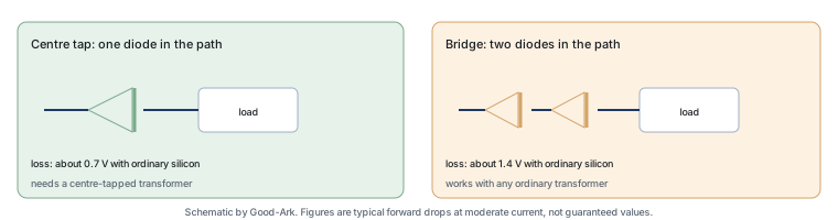
With two diodes in the conducting path, the voltage lost is roughly twice the forward drop of one device. For ordinary silicon diodes at around 0.7 volts each, that is about 1.4 volts. For Schottky diodes at around 0.4 volts, it is about 0.8. The bridge’s four-diode arrangement therefore costs roughly double what a centre-tapped two-diode arrangement costs in lost voltage.
Whether that matters depends entirely on the scale of the circuit. In a 300 volt supply, 1.4 volts is a rounding error and the transformer saving dominates. In a 5 volt supply, 1.4 volts is more than a quarter of the output, which is why low-voltage designs often use a different approach altogether — a centre-tapped arrangement, a Schottky bridge, or active rectification with MOSFETs that behave like diodes with almost no drop.
There is one more accounting detail that surprises people: the loss is not proportional to the number of diodes in the package, it is proportional to the number in the path. The other two diodes are reverse biased and dissipating almost nothing, so a bridge with four diodes does not cost four times a single diode. It costs twice, because two are conducting and they are in series.
| Arrangement | Diodes | Drops in the path | Transformer requirement |
|---|---|---|---|
| Half-wave | 1 | 1 | None, but half the waveform is wasted |
| Centre-tap full-wave | 2 | 1 | Centre-tapped secondary |
| Bridge full-wave | 4 | 2 | Any ordinary secondary |
| Three-phase bridge | 6 | 2 per path | Three-phase supply |
Three external references help with the design decisions this article raises. The rectification principle is described under rectifiers, the bridge arrangement under diode bridge, and the three-phase case that appears in industrial drives under three-phase electric power. Component test methods come from JEDEC, assembly and thermal expectations from IPC, and sector-level context from the Semiconductor Industry Association. Device and assembly background is published by ISO, NIST and IEC.
When three or six diodes appear
Other counts exist for other reasons. A three-phase bridge uses six diodes because it has three inputs rather than two, and the extra count buys a much smoother output: the three phases deliver power in overlapping turns, so the gaps between pulses nearly disappear and the filter can be smaller. That is why industrial drives and high-power supplies work from three-phase supplies wherever they can.
Voltage multipliers use more diodes still, arranged so that capacitors are charged in parallel and discharged in series, producing outputs far above the input voltage. Those circuits use diode counts in the tens, and their purpose is different again. The count is always answering a specific requirement: transformer type, output smoothness, or output voltage.
One-page summary
One diode rectifies half the waveform and wastes the other half. Two diodes rectify the whole waveform but require a centre-tapped transformer whose copper is used inefficiently. Four diodes rectify the whole waveform with an ordinary transformer, at the cost of an extra diode drop in the conducting path. The two extra diodes do not add a function; they remove a constraint, and that constraint was expensive enough to be worth paying for in voltage.
FAQ
How many diodes are needed for a bridge rectifier?
Four, for a single-phase supply. The count comes from needing one pair to route each end of the winding to the positive output and another pair to route each end to the negative output. A three-phase bridge needs six for the same reason applied to three inputs rather than two, and a voltage multiplier can use many more.
What are the disadvantages of bridge rectifiers?
Two device drops in the conducting path rather than one, which costs roughly 1.4 volts with ordinary silicon diodes and matters most at low output voltages. Four devices instead of two, with the corresponding thermal load concentrated in one package. And the current peaks drawn by the smoothing capacitor are high, which stresses the diodes and complicates the thermal design. None of those outweighs the transformer saving in mains-powered equipment, which is why the arrangement dominates there.
Can you explain how a bridge rectifier works?
Briefly: the four diodes are connected so that whichever way the input current arrives, it is routed to leave at the same output terminal, which is why the output always flows in one direction. The full explanation, with the current path traced for each half of the cycle, is in our article on what a bridge rectifier is.
How do I select diodes for a bridge rectifier?
Three ratings decide it. The reverse voltage rating must exceed the peak of the incoming waveform with margin for transients, which means sizing against the peak rather than the nominal value. The average forward current must cover the load current derated for the actual case temperature. And the surge rating must cover the inrush when the smoothing capacitor charges at switch-on, which is often the largest current the diodes will ever see.
Would a Schottky bridge be better?
At low output voltages, often yes, because halving the drop from about 1.4 volts to about 0.8 is a large fraction of the output. At mains voltages it rarely matters, because 1.4 volts is negligible against hundreds of volts and the Schottky’s lower voltage rating becomes a liability rather than an advantage.
What to do next
The next useful step is to work out which of the three arrangements suits a supply you are looking at: the transformer you have, the output voltage you need and the room available in the enclosure usually decide it between them. Our articles on the bridge principle and on bridge packages and ratings cover the other two angles, and the families are grouped in the product family learning centre.
Tell Good-Ark the input voltage, the required output and the transformer you have, and we can point to the bridge family and rating class that fit.
Email sales@goodark.com, or start from the bridge rectifier overview.
This article is published by Good-Ark, a manufacturer of bridge rectifiers and other discrete devices. Forward voltage figures are typical values given for illustration; the ratings that apply to a specific part come from its official datasheet.
Recommended
 Why Do Diodes Get Hot? Conduction and Switching Losses ExplainedInfoStandard, Fast Recovery, and Schottky Diodes: What’s the Difference?Info
 What Is a Fast Recovery Diode? Understanding “Fast Recovery”Info
 What Is a Diode? A Beginner’s Guide to How It WorksInfo
 Automotive Semiconductor Report 2026: Chips Per Car Keep RisingKnowledge