What Is the GSMDJ Series Used For?
Pick a TVS by standoff voltage and the surge you actually expect: 600 W versus 350 W at temperature, leakage at 85 C, and the clamping arithmetic.

The GSMDJ Series is designed for surge and transient-voltage protection in power and electronic circuits. It helps clamp harmful voltage spikes before they reach sensitive components, supporting dependable operation in industrial equipment, power supplies, automotive electronics, communications hardware, and renewable-energy systems. Correct selection depends on working voltage, clamping voltage, surge capability, package, polarity, and circuit placement.
Last updated:
Key Takeaways
- The GSMDJ Series is designed for surge and transient-voltage protection in power and electronic circuits.
- Before you finalize the BOM, compare the related options: What Is the GSMDJ Series Used For? and What Is the GSD Series?.
- Verify your choice against official product data and application guidance: Good-Ark product families and Good-Ark new releases.
What Is the GSMDJ Series?
The GSMDJ Series is a family of transient-voltage-suppression devices intended to protect electronic circuits from short-duration overvoltage events. It is commonly applied where systems face electrostatic discharge, inductive switching spikes, lightning-related surges, or other transient disturbances.
A TVS protection device normally remains in a high-impedance state during normal operation. When voltage rises above its breakdown threshold, it conducts rapidly and diverts surge current away from protected circuitry. This behavior limits the voltage seen by downstream semiconductors, ICs, MOSFET gates, data interfaces, and power-management components.
For designers, the series designation alone is not enough for final selection. The exact part number, suffix, unidirectional or bidirectional configuration, standoff voltage, peak pulse power rating, and package thermal characteristics must be verified in the applicable product datasheet.
Good-Ark Electronics supports a broad portfolio of protection semiconductors, including TVS, ESD, and Zener devices for power, automotive, industrial, lighting, consumer, and communication applications.
How Does the GSMDJ Series Protect Circuits?
The GSMDJ Series protects circuits by responding quickly when transient voltage exceeds the device’s breakdown level. It conducts surge current through the protection path, reducing the peak voltage delivered to vulnerable components.
During normal operation, the device should not significantly affect circuit performance. During a surge, however, its nonlinear voltage-current characteristic becomes active. As surge current increases, the device clamps the line near its specified clamping-voltage range. The protected load therefore experiences less electrical stress.
A TVS diode does not eliminate surge energy; it redirects and absorbs a controlled portion of that energy. The PCB copper, ground return, upstream fuse or protection element, and enclosure design also influence the final protection result.
Which Electrical Ratings Matter Most?
The most important ratings are reverse standoff voltage, breakdown voltage, clamping voltage, peak pulse current, peak pulse power, leakage current, capacitance, and operating temperature range. These values should be selected according to the protected line rather than by package appearance alone.
Start with the maximum normal voltage that may exist on the circuit, including supply tolerance, charging voltage, ripple, load-dump conditions, switching overshoot, and abnormal but non-destructive operating states. The selected TVS device must have a reverse standoff voltage above this maximum steady-state value.
Next, compare the specified clamping voltage with the maximum voltage that the protected semiconductor can survive. A device may have adequate surge-power capability but still provide poor protection if its clamp voltage exceeds the protected component’s safe limit.
Leakage current becomes especially important in battery-powered, precision-sensing, high-impedance, and low-power products. Junction capacitance matters in high-speed signal paths, where excessive capacitance can distort waveforms, degrade eye diagrams, or limit communication bandwidth.
Good-Ark Electronics product-selection support can help engineers compare protection requirements with package, voltage, current, and thermal constraints before prototype release.
Where Can the GSMDJ Series Be Used?
The GSMDJ Series can be used near vulnerable power inputs, DC rails, relay and solenoid interfaces, motor-control lines, communication ports, LED drivers, photovoltaic electronics, and industrial I/O circuits. The best location is generally close to the surge-entry point or the component requiring protection.
Common applications include:
-
Switched-mode power supply input and output protection
-
DC/DC converter input protection
-
Automotive low-voltage and body-electronics circuits
-
LED lighting drivers and outdoor lighting systems
-
Solar inverter auxiliary circuits and photovoltaic combiner equipment
-
Industrial controls, PLC interfaces, sensors, and actuators
-
Consumer appliances and home-electronics power rails
-
Telecom and communication-system DC power interfaces
For an AC input, a TVS device may work alongside a fuse, MOV, gas discharge tube, bridge rectifier, common-mode choke, and safety capacitor. For a DC rail, it may be paired with reverse-polarity protection, a fuse, an eFuse, a MOSFET, or a current-limiting resistor.
The protection network should be designed as a system. A TVS diode is highly effective when it is properly rated, correctly located, and coordinated with the rest of the circuit’s energy-handling elements.
Why Is Correct TVS Selection Important?
Correct TVS selection is important because an undersized device can fail during a surge, while an incorrectly chosen voltage can create leakage, unwanted heating, false triggering, or inadequate clamping. Protection must match both the normal operating conditions and the actual surge environment.
A low standoff-voltage device may begin conducting during routine voltage peaks. This can raise device temperature, increase standby loss, and shorten product life. Conversely, a device with an excessively high clamping voltage may allow damaging energy to reach sensitive MOSFETs, controllers, sensors, or capacitors.
Selection should also consider the source of the surge. A long, high-energy event from a power line differs from a fast ESD event at a user-accessible connector. The waveform, source impedance, repetition rate, ambient temperature, and available board area can all change the appropriate solution.
Engineers should avoid treating peak pulse power as a universal guarantee. It is normally specified under defined laboratory pulse conditions. Real applications may involve repeated surges, elevated temperatures, poor heat dissipation, or nonstandard pulse shapes that require additional design margin.
Decoding a member part number
Within a family, a specific member is identified by its complete orderable part number including the suffix, and the ordering-information table is what converts that string into a specification. The table tells you which voltage class, which package and which grade the string refers to, and it is the only authoritative decoder.
The method is uniform across manufacturers. Read the complete number from the package, find the family from its prefix, find the matching row, then check the marking specification to confirm the printing on your part corresponds to that row. Our article on decoding the GS prefix sets the method out in full.
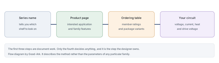
One more point belongs in the short answer, because it affects how much time you spend. The question “what is this family used for” is answered by two documents that take about ten minutes to read together, and it is worth doing that before reading any comparison or review. Secondary descriptions, including catalogues and articles like this one, are useful for method and useless for specifics — they cannot be more current than the manufacturer’s own page, and they are frequently less so.
The habit that follows is to treat any family name as a search term rather than as a description. Searching it should take you to a product page, and the product page should take you to a datasheet with a revision date. If the chain ends somewhere else — a marketplace listing, a datasheet archive, a forum thread — you have found something useful for a different purpose, but you have not yet established what the family is for.
Distinguishing it from neighbouring series
Sibling families are the most common source of confusion, because a code that looks familiar may belong to a family developed separately. Three differences matter when comparing them. The families may number their members differently, so a digit does not carry the same meaning across both. They may occupy different voltage territories, so a part that looks equivalent may be specified for a different class. And they may differ in qualification or grade, which matters in applications where evidence has to be provided.
The comparison method is the same four columns used elsewhere: blocking voltage range, package options, application territory and available qualification evidence. Those four show immediately whether two families overlap and where the boundary runs, without any reliance on the names.
How Should Engineers Select a GSMDJ Series Device?
Engineers should select a GSMDJ Series device by defining the protected line’s maximum steady-state voltage, acceptable clamp voltage, expected surge waveform, peak current, repetition level, polarity requirement, and board-layout constraints. The selected part should then be validated through application-level testing.
Use this practical selection sequence:
-
Identify the normal maximum voltage on the line, not just the nominal supply voltage.
-
Select a reverse standoff voltage that remains above all normal operating conditions.
-
Determine the maximum safe voltage of the component being protected.
-
Check whether the TVS clamping voltage remains below that safe limit at the expected surge current.
-
Confirm the peak pulse-current and power ratings for the relevant transient waveform.
-
Choose unidirectional protection for many DC applications and bidirectional protection where the signal or line reverses polarity.
-
Verify leakage, capacitance, package size, creepage, clearance, and thermal conditions.
-
Test the complete assembled board using realistic surge and ESD conditions.
For example, a 24 V industrial rail can experience higher voltage because of tolerance, switching, cable inductance, and load transients. A protection device should therefore be selected for the real maximum operating voltage and the actual fault environment, not simply because “24 V” appears on the product label.
Can PCB Layout Improve Surge Performance?
PCB layout can substantially improve surge performance because trace resistance and inductance add voltage during fast transient events. A correctly selected TVS diode can still underperform if it is connected with long, narrow, or poorly grounded traces.
Place the GSMDJ Series device as close as possible to the connector, power-entry point, or exposed interface where the surge enters. Use short, wide copper connections to the protected line and ground or return plane. Minimize loop area between the TVS diode, connector, and return path.
Avoid routing the surge current through sensitive ground regions. Where practical, separate the high-current surge-return path from analog reference grounds, high-speed signal returns, and control-circuit grounds. This reduces the chance that a transient creates a ground bounce that disrupts logic or measurement circuits.
After layout completion, review the current path visually. Ask where the surge enters, where it is diverted, and whether the shortest route leads directly through the TVS device to the intended return path.
How Do You Choose the Clamping Voltage Rather Than the Standoff Voltage?
The standoff voltage sets whether the device is safe in normal operation; the clamping voltage sets whether the protected circuit survives a surge. Engineers usually pick the first and hope for the second, which is where most TVS selection goes wrong.
A production TVS family shows how far apart the operating points are. ST specifies the SMBJ series for 600 W of peak pulse power on a 10/1000 µs waveform and 4 kW on an 8/20 µs waveform, with standoff voltages from 5 V to 188 V, leakage of 0.2 µA at 25 °C rising to 1 µA at 85 °C, and a maximum junction temperature of 150 °C. The same family is rated up to 350 W at that junction temperature — a 42% reduction from the headline figure once the die is hot.
| Parameter | Value | Why it changes the part you pick |
|---|---|---|
| Peak pulse power | 600 W (10/1000 µs), 4 kW (8/20 µs) | The number is meaningless without the waveform; a long pulse is a much harder test |
| Power at Tj max | up to 350 W | Derate before comparing against your surge |
| Leakage current | 0.2 µA at 25 °C, 1 µA at 85 °C | A five-fold rise matters on battery and sensing rails |
| Standoff range | 5 V to 188 V | Pick the lowest standoff that still clears the real rail maximum |
| ESD / EFT immunity | IEC 61000-4-2 to 30 kV contact and air; IEC 61000-4-4 level 4 | Tells you the standard the part was characterised against, not just the wattage |
Turn that into a selection sequence. First, establish the real maximum continuous voltage on the rail — a 24 V industrial supply is not 24 V once tolerance, ripple, and load transients are included — and pick the lowest standoff voltage that clears it with margin. Second, estimate the surge current you actually have to survive and match the waveform, not just the wattage. Third, multiply the clamping voltage by that current and compare the result against both the headline rating and the derated rating at your worst-case ambient. Fourth, check that the clamping voltage still leaves every protected device inside its own absolute maximum. A part that survives the surge but clamps above the IC’s rating has not protected anything.
The leakage figure deserves its own check on sensing and battery-powered inputs, because the 25 °C number is roughly a fifth of the 85 °C number in the same datasheet. On a high-impedance node, that difference is a real offset, and it applies whether or not a surge ever occurs.
When Should a GSMDJ Series Device Be Tested?
A GSMDJ Series device should be tested during prototype validation, before design release, after layout changes, and whenever the end-product environment changes. Datasheet checks are essential, but they do not replace testing in the actual circuit.
Testing should include realistic operating voltage, temperature, load conditions, cable configuration, and surge source conditions. Depending on the application, engineers may evaluate ESD immunity, electrical fast transients, surge pulses, inductive-load switching, reverse battery, load dump, or repetitive switching stress.
Inspect the protection device and surrounding components after testing. A TVS device may not visibly fail even if its electrical characteristics have drifted. Measure leakage current, breakdown behavior, clamp response where possible, and system functionality before and after exposure.
For high-reliability applications, include worst-case conditions such as maximum ambient temperature, minimum and maximum supply voltage, long cable lengths, repeated transient events, and tolerance stack-up. This process helps ensure that protection performance remains dependable beyond a laboratory demonstration.
FAQs
What is the difference between standoff voltage and clamping voltage?
Standoff voltage is the highest continuous voltage the device can block without conducting, so it must sit above the real maximum of the rail you are protecting. Clamping voltage is the voltage that appears across the device during a specified surge current, so it decides whether the protected circuit survives, and it is always higher than the standoff value.
Can I compare a 600 W TVS with a 400 W TVS directly?
Only if the pulse waveform and the junction temperature are the same. Peak pulse power is specified for a waveform such as 10/1000 microseconds, and the same family can be rated far lower once the die is at its maximum junction temperature. Match the waveform, then derate for temperature, then compare.
Does TVS leakage matter if the rail is not battery powered?
It matters most on high-impedance nodes, sensing inputs, and standby paths. A datasheet may quote leakage at 25 degrees Celsius and again at a much higher temperature, and the difference between those two conditions is what you must check against the circuit error budget.
Where should a TVS be placed on the board?
As close to the connector or entry point as the layout allows, with a short, wide path on both sides and a low-impedance return. Placed further downstream, the surge has already propagated past the devices you were trying to protect.
Related Articles
Official Resources
References
- All About Circuits – Transient Voltage Suppressors (TVS): An Introduction
- IEC 61643-11:2025 – Surge protective devices connected to low-voltage power distribution systems
- JEDEC JC-22 – Discrete diode and thyristor standardization committee
- Power Electronics News – Power Electronics Course with QSPICE: TVS Diodes and MOV Varistors
- Power Electronics News – TVS Diodes Protect Electronics from Voltage Transients
Continue through this engineering topic
For the complete selection, design, verification, and troubleshooting path, explore the Good-Ark Product and Sourcing Hub.
- Practical guide: Good-Ark Semiconductor: A Practical Guide to Sourcing Discrete Devices
- Practical guide: Solar Inverter Component Selection Guide Design Choices and Supplier Evaluation
- Practical guide: The Good-Ark Product List You Already Own: Ten Everyday Gadgets and the Parts Inside Them
- Ask Good-Ark technical support about this application
Recommended
 Why Do Diodes Get Hot? Conduction and Switching Losses ExplainedInfoStandard, Fast Recovery, and Schottky Diodes: What’s the Difference?Info
 What Is a Fast Recovery Diode? Understanding “Fast Recovery”Info
 What Is a Diode? A Beginner’s Guide to How It WorksInfo
 Automotive Semiconductor Report 2026: Chips Per Car Keep RisingKnowledge