What Is an FRD Diode? Fast Recovery Explained for Power Circuits
Two diodes can have the same average-current rating and behave differently during a 100 kHz switching cycle. At that illustrative frequency, one…

Two diodes can have the same average-current rating and behave differently during a 100 kHz switching cycle. At that illustrative frequency, one complete cycle lasts 10 µs. A transition that looks brief on a clock can still drive a significant current spike when repeated many times.
An FRD diode is selected for what happens during that transition as well as during ordinary conduction. The engineering decision is whether its complete recovery behavior, loss, voltage capability, and mounting conditions match the power circuit.
FRD diode: what fast recovery means in practice
An FRD diode is a fast-recovery rectifier intended to regain reverse-blocking behavior quickly after forward conduction. It is useful where switching repeatedly commutates diode current. Select it by documented recovery conditions, reverse charge, forward loss, voltage and current limits, and thermal requirements; the FRD label alone does not guarantee circuit compatibility.
Fast describes a behavior under specified conditions, not a universal frequency rating. Two devices carrying similar names can have different recovery charge, peak reverse current, and softness. Their forward-voltage and leakage tradeoffs may also differ. Read the selected manufacturer’s data instead of treating the abbreviation as a complete specification.
A useful comparison starts with the current path. Ask which switch forces the diode from forward conduction toward reverse bias, how rapidly that current changes, and what reverse voltage follows. Those circuit conditions explain why a recovery parameter matters.
Which recovery quantities belong in the comparison?
Reverse-recovery time, trr, describes a defined transition interval. Reverse-recovery charge, Qrr, describes charge associated with the reverse-current waveform. Peak reverse current and the shape of the current’s decay help explain stress and ringing. A short time by itself does not tell the whole story.
The onsemi reverse-recovery analysis in AN1520 illustrates the waveform and its measurement definitions. Compare definitions as well as values: endpoints, forward current, reverse voltage, current slew rate, and temperature must be compatible for a meaningful comparison.
Softness concerns how abruptly reverse current decays. A sharp current change interacting with loop inductance can contribute to voltage overshoot. A softer transition can help manage that behavior, while other losses and constraints still need review. The useful goal is an acceptable circuit waveform, not the smallest isolated timing number.
Separate maximum limits from typical curves. A typical recovery curve can guide an estimate, but a design requiring a guaranteed limit needs documentation and validation appropriate to that requirement.
Choose from the commutation path outward
Identify the interval during which the diode carries current and the event that ends it. A diode that naturally reaches nearly zero current before reverse voltage rises may face a different recovery burden from one that is forcibly commutated while carrying substantial current.
Record the expected forward current immediately before commutation, applied reverse voltage, switching rate, temperature range, and likely current slew rate. Then check the candidate’s recovery test conditions against those requirements. A timing value measured at a small current should not be transferred uncritically to a much larger load.
Next review forward loss and cooling. A fast device with unacceptable conduction loss is not an acceptable selection. Package geometry, mounting pressure where specified, thermal interface, and board or heatsink conditions determine how the dissipated power reaches the environment.
Pay attention to the temperature reference in each rating. A current specified at controlled case temperature is not automatically available in still air at the same ambient temperature. The junction-to-case path and the case-to-environment path are different parts of the thermal model. A comparison that omits the heatsink or board assumptions can make an electrically attractive candidate look much more capable than the installation allows.
The Analog Devices flyback-diode selection article connects recovery behavior with a practical converter context. Use topology-specific guidance without assuming that one converter’s stress equation applies unchanged to every power stage.
Compare standard recovery, FRD, and Schottky options
The choice is a set of tradeoffs. A standard-recovery rectifier can be suitable when rapid forced commutation is not a design requirement. A fast-recovery PN diode targets switching behavior while retaining other constraints. A Schottky uses a different junction mechanism and still has capacitance, leakage, and thermal limits.
| Candidate | Potential reason to choose it | What must still be checked | Misleading shortcut |
|---|---|---|---|
| Standard-recovery silicon rectifier | General-purpose rectification under suitable waveforms | Current, voltage, surge, heat, and any commutation demands | High reverse rating means fast switching |
| Fast-recovery PN rectifier | Documented recovery for switching current paths | Charge, peak current, softness, forward loss, test conditions | Shortest trr is always the right choice |
| Silicon Schottky rectifier | A favorable conduction and switching tradeoff in an appropriate voltage range | Hot leakage, capacitance, reverse rating, thermal behavior | No stored-charge tail means no switching effects |
The UF4001–UF4007 ultrafast rectifier datasheet gives an example of explicit recovery test conditions. The 1N5817–1N5819 Schottky datasheet illustrates a separate family with its own blocking and forward characteristics. Compare the actual candidates rather than extending those examples into universal limits.
Why a faster diode can still produce an unhappy waveform
Layout inductance and current slew rate can dominate overshoot. A diode’s abrupt recovery can interact with the switch, package, interconnect, and capacitances. Replacing the diode may change ringing without removing the physical loop that supports it.
A second mistake is considering only diode heating. Recovery current can increase stress and loss in the commutating switch. The TI discussion of output charge and reverse-recovery charge explains why charge-related behavior matters in the surrounding switching system.
A third mistake is comparing trr at unlike conditions. Different forward currents, current slopes, temperatures, or endpoints can reverse an apparent ranking. Copy the conditions into the comparison worksheet rather than leaving them in a footnote that disappears when the table is shared.
Do not assume a part with a familiar package also has the same internal diode arrangement. Dual common-cathode devices and single junctions require different pin and current-path checks. Physical fit cannot settle those electrical differences.
Verification: separate static screening from dynamic testing
A handheld diode test can reveal some gross faults and help confirm an isolated junction’s forward direction. It cannot measure nanosecond recovery, reverse charge, or circuit ringing. The Fluke diode-testing guide describes the basic unpowered measurement; keep its conclusion within that scope.
Dynamic validation needs a defined circuit, current and voltage waveforms, temperature context, and a suitable measurement arrangement. Probe loop inductance and bandwidth can distort the transition you want to observe. Establish the test method before declaring that a waveform change comes from the device.
For a rough system-level estimate, assume a recovery-associated switching energy of 10 µJ per event and 50,000 relevant events each second. Multiplying energy by event rate gives 0.5 W. These invented values are an arithmetic example, not product data. Actual energy must come from an applicable measurement or model and must be assigned to the correct device or system loss mechanism.

How the diode connects to nearby power parts
The standard versus fast-recovery comparison is the next step when deciding whether a switching requirement exists at all. For larger packages, the TO-247 fast-recovery diode guide and TO-220 fast-recovery diode guide connect electrical selection with mounting constraints.
A suppressor has another job. The TVS explanation describes transient clamping, which should not be inferred from an FRD’s reverse-voltage rating. A rectifier’s ability to block a specified voltage does not establish a controlled protection threshold.
The commutating transistor, gate-drive setting, and freewheel path form one system. Changing the diode can shift a waveform or loss distribution elsewhere. Keep those interacting parts in the validation plan rather than testing the rectifier as though its package were the whole circuit.
A practical FRD comparison checklist
Make the selection record specific enough for another engineer to repeat. Identify the circuit role, manufacturer, full order code, package, internal configuration, and expected temperature range before listing attractive headline values.
- Match forward current and reverse stress to the actual waveform.
- Copy trr and Qrr conditions with their values.
- Review recovery-current shape and peak stress where relevant.
- Estimate conduction and switching-related loss separately.
- Check thermal mounting and electrical isolation requirements.
- Validate startup, load range, temperature, and relevant commutation events.
If a required condition or guarantee is missing, keep it as an unresolved selection item. Do not replace it with an assumed conversion from another manufacturer’s typical curve or an unrelated test.
When the next step is the exact datasheet
Read the datasheet as soon as you move from explaining FRD behavior to choosing a part. The abbreviation does not define a pinout, a current limit, a universal maximum frequency, or a permitted mounting temperature. Those belong to the selected component and application.
For a replacement, compare the original and candidate at compatible conditions and keep the waveform evidence with the approval record. The successful outcome is a diode that meets the circuit’s switching, conduction, and thermal needs together. A smaller recovery-time number is useful only when that broader requirement is satisfied.
FAQ
Does FRD mean a particular reverse-recovery time?
No. FRD describes a fast-recovery rectifier category, while a particular device datasheet provides the timing value and its test conditions. Compare forward current, reverse voltage, current slew rate, temperature, and the measurement endpoint before ranking two parts. A shorter number measured under easier conditions does not establish better behavior in your circuit. The full operating requirement still controls the choice.
Is a Schottky always better than an FRD?
No. The useful choice depends on blocking voltage, forward loss, leakage at temperature, capacitance, current waveform, thermal conditions, and circuit cost constraints. A Schottky can offer a favorable tradeoff in an appropriate application, but its technology name does not establish suitability. Compare specific candidates and verify the complete circuit behavior, especially when a substitution changes ringing, hot leakage, or the surrounding switch stress.
Can a multimeter prove that an FRD is still fast?
No. Diode mode applies a small test stimulus and measures a static or slowly established junction response. It can help find a gross short or open and support polarity identification, but it does not reproduce a switching commutation event. Recovery time, reverse charge, and ringing require suitable dynamic measurements under defined conditions. Keep a basic junction screen separate from operating qualification.
Explore the related topic guides
Continue with the related selection, design and verification guides:
Recommended
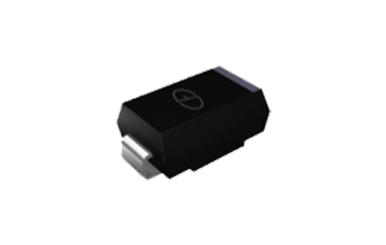 ES1J and UF5408: Picking a Fast or Ultrafast Axial RectifierKnowledge
 MUR2060CT and MUR3040PT: Dual Ultrafast Rectifiers in Power StagesKnowledge
 MBR40100CT and MBR30100PT: Reading Dual Schottky Part NumbersKnowledgeMUR120 Fast Recovery Diode: Specs, Role, and Substitution BoundsKnowledge
 MBRF20200CT Explained: Dual Schottky Ratings and Typical UsesKnowledge
 1N4007 vs 1N4148: Rectifier vs Switching Diode (Do Not Swap Blindly)Knowledge