Zener Diode for Beginners: Regulating a Voltage Without an IC
Zener diode for beginners: a five-component circuit that holds a voltage steady, why the series resistor is not optional, and what happens when the load shifts.
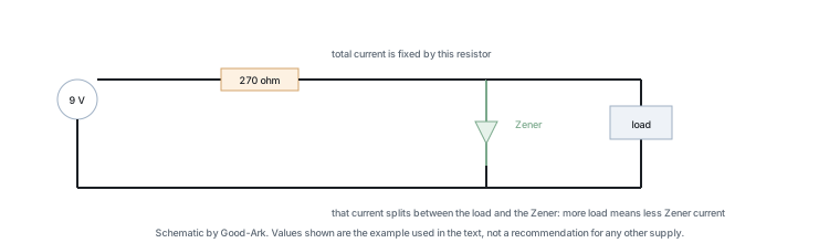
This is the smallest useful voltage regulator you can build: a resistor, a Zener diode, and something to power. It is not accurate and it is not efficient, and it will teach you more about regulation than any explanation, because you can watch the output move as you change the load.
What you will build
A circuit that takes a supply higher than the voltage you want — a nine volt battery is convenient — and delivers a steady output at the Zener voltage. The Zener sits in parallel with the output, and a resistor sits between the supply and the Zener. The load connects across the Zener.
What makes it a regulator is the interaction between the two components. If the output voltage tries to rise, the Zener conducts more and pulls it back down. If the load draws more current, the Zener conducts less and the output stays where it was. The resistor is what makes that interaction possible, because it converts any voltage difference across it into a current, and that current has to go somewhere.
Parts you need
Five items, none of them expensive. A supply above the target voltage, a Zener diode of the voltage you want, a series resistor, a load, and a meter to see what happens. The example values below assume a nine volt supply, a 5.1 volt Zener and a load that draws about ten milliamps.
| Item | Example value | Why this value |
|---|---|---|
| Supply | 9 V | Comfortably above the target, and a common battery |
| Zener diode | 5.1 V, quarter watt or better | A common value near the most temperature-stable band |
| Series resistor | About 270 ohms | Carries the Zener current plus the load current at the voltage difference |
| Load | About 10 mA | Small enough to stay inside the Zener’s power rating |
| Meter | Any multimeter | To check the output as the load changes |
Why the series resistor exists
The resistor sets the current. The voltage across it is the supply voltage minus the Zener voltage, which in this example is about 3.9 volts. The current through it is that voltage divided by the resistance, so a 270 ohm resistor carries roughly fourteen milliamps. Of that, ten milliamps goes to the load and the rest, about four, flows through the Zener.
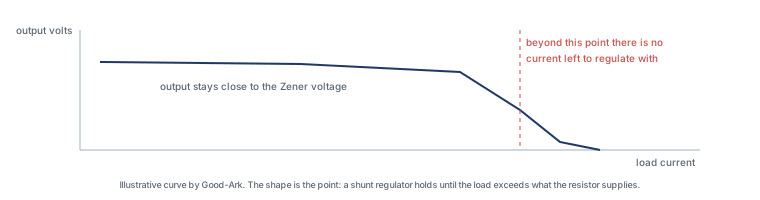
Now change the load. If the load draws nothing, all fourteen milliamps flows through the Zener, and the diode has to dissipate about 5.1 volts times fourteen milliamps, which is roughly seventy milliwatts — comfortably inside a quarter watt part. If the load tries to draw more than fourteen milliamps, the output voltage collapses because there is no current left for the Zener to regulate with. That is the essential limit of this circuit, and it is why the resistor value is chosen from the worst-case load current rather than from a convenient number in a drawer.
Wiring it step by step
Work with the supply disconnected. Identify the Zener’s cathode — the banded end, the same convention as any other diode — and note that it connects toward the positive rail, which is the opposite of what a beginner expects from the word “breakdown”. Connect the supply positive through the resistor. Connect the resistor’s far end to the Zener cathode and to the load. Connect the Zener anode and the load return to the supply negative.
Before applying power, check three things. That the Zener is the right way round, because reversing it turns the circuit into a crude 0.7 volt clamp. That the resistor is the value you calculated rather than one that happened to be within reach. And that nothing is bridged across the resistor, which would remove the current limit entirely.
Measuring the result
Connect the meter across the output and apply power. You should read something close to the Zener voltage, not exactly on it, because the diode’s tolerance and the small current dependence both move it. Then check the voltage across the resistor: it should be roughly the supply voltage minus the output, and if it is not, one of your assumptions is wrong.
The most instructive measurement is the current through the resistor, which you can find by measuring the voltage across it and dividing by its resistance. Compare that with the current the load draws. The sum should match, and watching that balance move as you change the load is the whole lesson of the circuit.
What changes when the load changes
Three behaviours are worth observing, because they are the ones that explain why this circuit is rarely used for anything demanding.
First, the output voltage moves slightly with load. As the load draws more current, the Zener current falls, and because the Zener’s holding voltage depends a little on current, the output sags. That dependence is the Zener’s dynamic resistance, and it is why a one per cent reference needs a different device.
Second, the voltage moves with temperature. In the five to six volt region the drift is small because two breakdown mechanisms partly cancel, and away from that region it is larger. An experiment with a hairdryer or a freezer pack on the Zener will show it, and the movement is the reason precision references are temperature-compensated.
Third, the circuit wastes current by design. Whatever the load does not use flows through the Zener as heat. At full load the efficiency is reasonable; at no load, the entire supply current is being turned into heat for nothing. That is the fundamental trade of a shunt regulator, and it is why switching regulators displaced it in anything battery powered.
If you want to check the behaviour against an external source, the device is described under Zener diodes, the linear alternative under linear regulators, and the switching alternative under switched-mode power supplies. Component measurement methods come from JEDEC, assembly and thermal expectations from IPC, and sector-level context from the Semiconductor Industry Association. Device and assembly background is published by ISO, NIST and IEC.
Safety notes for beginners
Build the circuit at low voltage — a battery, not a mains adapter — and disconnect the supply before changing anything. A Zener in a circuit that is fed from the mains can sit at a dangerous potential, and the smoothing capacitors nearby hold charge after the plug is removed.
It is also worth building the habit of checking the resistor before the diode. The resistor is what sets every current in the circuit, so a wrong value makes the Zener’s dissipation wrong, and the diode is usually the part that fails as a result. Measuring the resistor with a meter before soldering it takes a few seconds and removes the most common cause of a hot component in this circuit.
Watch the Zener’s temperature during the experiment. A quarter watt part running at seventy milliwatts is comfortable, but the same part in a circuit where the resistor is much smaller can exceed its rating quickly, and a Zener that fails short will then pull the supply down and may damage what follows. If the diode becomes too hot to hold briefly, the resistor value is wrong rather than the diode.
Where to go next
Once the circuit works, the natural next steps are to replace the Zener with a three-terminal linear regulator and compare the output stability, and then to try a switching module and compare the efficiency. Both experiments make the trade-offs between the three approaches obvious in a way that reading cannot. The device background is in our article on Zener diodes in plain language, and the wider context is in the product family learning centre.
FAQ
What is a Zener diode in a simple way?
It is a diode that is meant to conduct in the reverse direction at a chosen voltage and to hold that voltage while it does. An ordinary diode is destroyed if you push it that far; a Zener is built so that the same event is its normal working condition. Connect it across a supply through a resistor and it will hold the output near its rated voltage.
How do I choose the right Zener diode?
Start from the voltage you want to hold, then check the tolerance and the temperature behaviour, because both move the actual level away from the nominal value. Then calculate the worst-case current the diode will have to absorb, which is the current through the series resistor when the load draws nothing, and pick a power rating with margin above it. A part that holds the right voltage but overheats at no load is not the right part.
What are the disadvantages of using a Zener diode for regulation?
Three. The output is not accurate, typically within a few per cent and moving with temperature. The circuit wastes current continuously, because whatever the load does not take flows through the diode as heat. And it can only supply as much current as the series resistor provides, so its capacity is set by a resistor rather than by the device. Our comparison of Zener and TVS behaviour covers the adjacent question of when a Zener is the wrong family entirely.
Can a Zener diode handle AC voltage?
It will clamp both halves of an alternating waveform, but at different levels, because one direction is ordinary forward conduction at around 0.7 volts and the other is Zener conduction at the rated voltage. For a symmetric clamp you need two Zeners back to back, or a device built for the purpose. In a regulator circuit the input is direct current by definition, so the question usually comes up when someone tries to build a mains-side clamp.
Why does my output voltage drop when I connect a load?
Almost always because the load is drawing more current than the series resistor supplies. Once the load takes the entire current, the Zener has nothing to regulate with and the output simply follows the load down. The fix is to reduce the resistor value so more current is available — and then to check that the Zener can still dissipate the extra current at no load.
What to do next
Recalculate the resistor for a supply and a load you actually have, and note how the two worst cases — no load and full load — set the limits on the value. That pair of constraints is the whole design of a shunt regulator, and recognising it will save you from a circuit that works on the bench and fails in the product.
Tell Good-Ark the voltage, the worst-case current in both directions and the accuracy you need, and we can point to the family and power class that hold it.
Email sales@goodark.com, or start from the product family learning center.
This article is published by Good-Ark, a manufacturer of Zener and other discrete devices. The component values are a worked example for a low-voltage bench experiment, not a design recommendation; verify the current and power in your own circuit before applying power.
Recommended
 Why Do Diodes Get Hot? Conduction and Switching Losses ExplainedInfoStandard, Fast Recovery, and Schottky Diodes: What’s the Difference?Info
 What Is a Fast Recovery Diode? Understanding “Fast Recovery”Info
 What Is a Diode? A Beginner’s Guide to How It WorksInfo
 Automotive Semiconductor Report 2026: Chips Per Car Keep RisingKnowledge