What Is a TVS Diode? Surge Protection Explained Simply
What is a TVS diode? It is an off switch that turns on when the voltage gets dangerous: what that means in a circuit, and what it cannot protect against.
Last updated:
The short definition is easy to find and does not help much on its own: a TVS diode is a component that conducts when the voltage across it becomes too high. The useful knowledge is knowing where “too high” sits relative to your circuit, and recognising the situations where a TVS is the wrong kind of protection entirely.
The one-line definition
A transient voltage suppressor is a semiconductor device that remains effectively open at normal circuit voltage and becomes a low-resistance path when the voltage rises above its breakdown point, diverting the excess energy away from the circuit it is protecting. It returns to its off state after the event, which is what distinguishes it from a fuse: the product keeps working.
There is a second half to the definition that datasheets reveal and marketing does not. A TVS does not hold the voltage at its rated level regardless of what arrives. It offers a lower and lower resistance as the current rises, so the voltage it clamps at depends on how much current the event pushes through it. That is why the clamping voltage on a datasheet always comes with a test current next to it.
Normal days versus bad days
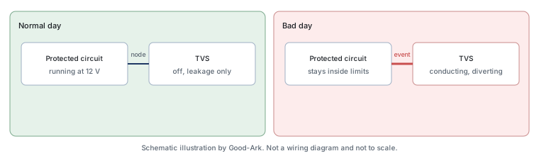
Think of the part as an off switch with a very specific trigger. On a normal day it is invisible: the circuit runs at its usual voltage, the TVS sits below its breakdown point and draws only leakage. On a bad day, the voltage climbs past the trigger and the switch closes, redirecting the event through a path that can survive it.
This is a different behaviour from regulation, and the distinction matters. A regulator actively holds an output at a chosen level during normal operation. A TVS does nothing during normal operation and acts only in an emergency. If you need the first behaviour, you want a regulator; if you need the second, you want a TVS. Confusing the two leads to a part that is either always conducting or never engaged.
How the voltage threshold works
Three voltage figures appear on a TVS datasheet, and reading them in the wrong order is the most common beginner mistake. The standoff voltage is the highest continuous voltage the part can sit at without conducting meaningfully; it must be above your normal rail including tolerance. The breakdown voltage is where conduction begins, specified over a range and at a test current. The clamping voltage is what your circuit actually experiences at a defined, much higher, pulse current.
Read them in that order, from the outside in. First check that the part is comfortably off during normal operation. Then check where it starts to conduct. Then check what it lets through. A part that passes the first check and fails the third is a part that will protect nothing, while appearing perfectly compliant on paper.
Surges that come from real life
The events a TVS is chosen for usually arrive from one of four directions. A person touches a connector, producing a fast static discharge. A cable picks up energy from a nearby lightning strike. An inductive load — a motor, a solenoid, a relay coil — is switched off and its stored energy has to go somewhere. Or a power source is disturbed, as when a load is disconnected from a car’s charging system and the voltage spikes before the regulator recovers.
These differ in duration by roughly six orders of magnitude, from tens of nanoseconds to tens of milliseconds, and energy scales with duration. That is why a part specified against static discharge is not automatically suitable for a load-dump event, even if its voltage rating looks generous. Matching the part to the threat means matching the waveform, not only the voltage.
Where a TVS is placed on a board
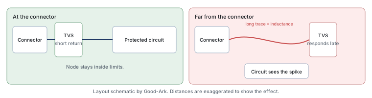
The device goes between the protected node and a low-impedance return, as close to the point where the threat enters as layout allows. In practice that means at the connector, with a short, wide path to ground. Distance is the enemy: every millimetre of trace between the connector and the protection adds inductance, and inductance converts a fast current into a voltage that appears across the very node you were protecting.
The second placement rule is about the return path. A protection device with a long, thin or shared return route will not clamp effectively, because the current has to complete a loop and the return is part of that loop. Designers who follow only the first rule and ignore the second often find that adding protection changed nothing at all.
There is a third consideration that is easy to miss because it is not about the TVS itself: whatever the device is protecting has to survive the clamped voltage, not the original spike. If the chip behind the connector is rated only slightly below the clamp level, the protection will work exactly as specified and the chip will still be stressed. The margin between the clamp and the circuit’s limit is the number that decides whether protection succeeded, and it is usually the number nobody writes down.
Three external references help when you want to check the claims on a datasheet or a supplier page. The device class is described in the transient voltage suppressors, and the consumer product that uses the same principle is covered under surge protectors. The test waveforms that make pulse ratings comparable come from the International Electrotechnical Commission, discrete device measurement methods from JEDEC, board-level assembly expectations from IPC, and industry-level reporting from the Semiconductor Industry Association. Standards and measurement background is published by NIST and ISO.
What it cannot protect against
A TVS handles short, high-voltage events. It is not a solution for sustained overvoltage, for reverse-polarity connection, for overcurrent, or for a device that is simply rated below the voltage it is being asked to work at. An event that lasts long enough to heat the part beyond its capability will destroy it, and a correctly sourced part then fails short and loads the supply — protection for the circuit, trouble for the product.
It also cannot compensate for a poor layout, as the figure above shows, and it cannot protect a signal whose integrity it has already ruined with capacitance. In those cases the part is genuinely doing its electrical job and the design still fails, which is confusing enough that it deserves saying plainly.
Two practical consequences follow from that list. The first is that a protection device is chosen against a waveform, not a voltage, so a supplier who quotes only a standoff voltage has told you almost nothing about whether the part will survive your event. The second is that the same part can be right for one node and wrong for the node next to it, because a rail with wide tolerance and a data pair with a narrow capacitance budget impose different constraints. When someone asks whether a particular TVS “works”, the honest answer is always: for which node, against which event.
TVS sizes in plain terms
| Where it is used | What matters most | What is usually sacrificed |
|---|---|---|
| A signal or data line | Low capacitance so the signal survives | Energy handling, which is small by design |
| A low-voltage power rail | Standoff close to the rail, low leakage | Some clamping headroom, because the margin is thin |
| A mains input | Energy handling and long-term stability | Size, cost and sometimes a second protection stage |
| A vehicle harness | Surviving repeated, specified transients | Physical size, and any hope of a low-cost part |
FAQ
What is the difference between a TVS diode and a normal diode?
A normal rectifier diode is built to conduct in the forward direction and block in reverse during ordinary operation, and it is not designed to absorb energy in reverse breakdown. A TVS is built specifically to conduct in that reverse region, dissipate the resulting energy and recover, which is why its datasheet describes pulse power and clamping behaviour instead of forward drop alone. A rectifier can survive a lucky surge; a TVS is specified to survive a defined one.
How to check if a TVS diode is bad?
Isolate the part from the circuit and measure with a diode test or resistance check in both directions. A TVS that has failed short reads as a near-short both ways, which is the most common failure and is easy to spot. A part that has degraded without failing cannot be identified this way, because its off state is unchanged and only its clamping behaviour has moved; that requires comparing it against a known-good part under pulse conditions.
What are the common causes of TVS diodes failing?
An event more energetic than the part was specified for, an event more frequent than its rated life allows, and heat. Overheating often comes from the part being run too close to its standoff voltage, so it leaks continuously, or from poor layout that prevents heat leaving the package. A TVS is also sometimes destroyed by an unrelated sustained fault, such as reverse polarity, that it was never designed to handle.
Where should TVS diodes be placed?
Between the node being protected and a low-impedance return, as physically close to the point where the threat enters as the layout allows, with a short and wide return path. For an external cable that means at the connector, not at the chip. When several lines share a connector, each line that crosses the boundary usually needs its own protection rather than one shared device.
Does a TVS replace an ESD protection diode?
Not always. They work on the same principle, but ESD protection parts are optimised for very fast, very low-energy events and for low capacitance, while a TVS for a power input is optimised for energy. On a high-speed data line, the ESD-optimised part is usually the correct choice; on a mains input, it is not. The SOD-523 ESD protection example shows what a data-line part looks like in practice.
What to do next
Write down the four parameters of the node you are protecting — normal voltage, maximum tolerable voltage, the event shape you expect, and how often it might repeat — and then choose. If the four numbers are not known yet, the part selection can wait; choosing a TVS first and fitting the circuit around it is how protection ends up nominal rather than real.
Send the node voltage, the event you expect and the part you are considering, and Good-Ark can tell you whether the rating class fits or what else needs defining first.
Email sales@goodark.com, or look at the TVS families first.
This article is published by Good-Ark, a manufacturer of protection devices. It explains the device class for readers without a design background; specifications, ratings and package options belong to the current official datasheet.
Continue through this engineering topic
For the complete selection, design, verification, and troubleshooting path, explore the TVS ESD and Surge Protection Hub.
- Practical guide: What Static Electricity Really Does to Your Electronics
- Practical guide: Zener vs Avalanche vs TVS for Spikes: The Clamping Family Nobody Names Correctly
- Practical guide: Low-Capacitance ESD Diodes: Protecting Signal Pins Without Blurring the Eye Diagram
- Ask Good-Ark technical support about this application
Recommended
 Why Do Diodes Get Hot? Conduction and Switching Losses ExplainedInfoStandard, Fast Recovery, and Schottky Diodes: What’s the Difference?Info
 What Is a Fast Recovery Diode? Understanding “Fast Recovery”Info
 What Is a Diode? A Beginner’s Guide to How It WorksInfo
 Automotive Semiconductor Report 2026: Chips Per Car Keep RisingKnowledge