AI Data Centers and Their Appetite for Power Semiconductors
AI data center power demand and semiconductors: why accelerator racks changed the architecture, what higher DC voltage does to losses, and what is uncertain.
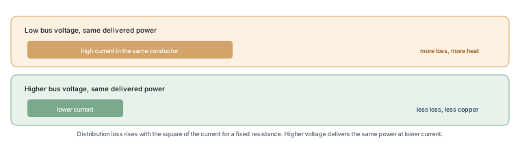
The demand that artificial intelligence places on a data centre is not really a demand for more electricity in the abstract; it is a demand for a great deal of power delivered to a small area, continuously, with a loss budget that has to be paid for twice — once as wasted electricity and once as heat that has to be removed. That combination is what changed the power architecture inside the building, and it is why the semiconductor content of a rack has grown.
Why AI changes rack power
A conventional server rack holds a number of general-purpose machines whose combined draw was, for a long time, modest enough that the electrical distribution inside the hall was not a design problem. An accelerator-dense rack concentrates far more computation into the same volume, and therefore draws far more current through the same physical space. Current, not voltage, is what sizes the copper, and it is also what turns distribution loss into a serious number.
The comparison that helps is water in a pipe. Doubling the flow through a fixed pipe roughly doubles the pressure drop at a given speed, but the friction loss rises with the square of the flow, so lines have to grow quickly or the losses become unacceptable. In electrical distribution the same relationship applies to current: loss rises with the square of current for a fixed resistance, which is the reason a higher distribution voltage is attractive, because the same power at a higher voltage means a lower current.
From 12 V to 48 V to DC distribution
A traditional server distribution bus inside the rack is a low voltage, historically 12 V, chosen because it is safe to work with and because the loads were small. As rack power rose, the current at that voltage rose with it, and the copper and the loss became the constraint. Moving the rack bus to 48 V reduces the current by a factor of four for the same power, and it has become a common design in high-density computing for that reason.
The next step in the same direction is distributing direct current at a higher voltage into the hall or to the rack, with a conversion stage placed close to the load. This is not new engineering — telecommunications facilities have distributed direct current for decades, and electric vehicles use high-voltage direct current buses — but it is a change from the alternating-current distribution that data centres inherited from general building practice. The trade is that conversion moves closer to the load, and a conversion stage has a cost, a loss and a failure rate of its own.
| Approach | What it buys | What it costs |
|---|---|---|
| Low-voltage rack bus | Simple, familiar, safe to service | High current, heavy copper, high distribution loss at high power |
| 48 V rack bus | Four times less current for the same power | Additional conversion stage between the bus and the load |
| Higher-voltage DC distribution | Lower current over longer distances | New protection and isolation practice, more conversion electronics |
Where efficiency losses become money
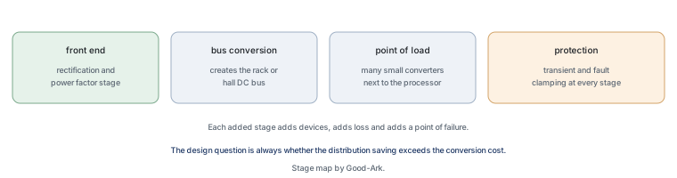
Every conversion stage loses a fraction of what passes through it, and a data centre converts energy several times between the incoming supply and a processor. Each stage’s loss is paid for twice: as electricity that was purchased and not used, and as heat that the cooling system has to remove, which itself consumes electricity. That double cost is why a small efficiency difference at a large scale becomes a visible operating expense rather than a rounding error.
It is also why the useful metric is not the efficiency of a single component but the efficiency of the path. A power supply that is efficient at full load and poor at light load looks good on a specification sheet and behaves differently in a facility where average load is well below capacity. That is the same lesson the 80 PLUS programme encodes for desktop supplies, extended to a much larger scale.
How much semiconductor content rises
More conversion stages mean more switching devices, more rectification and more control, so a rack designed around a higher-voltage DC bus contains more power semiconductors than one using a simple low-voltage bus. Three roles grow in particular. The rectification and power factor stage at the front end, which converts the incoming supply. The intermediate conversion stage, which creates the bus, and which is where wide bandgap devices are attractive because they can switch at a higher frequency with lower loss, allowing smaller magnetics. And the point-of-load stage, where many small converters sit close to the processors.
Protection grows with them. A higher-energy bus needs devices that can absorb more energy during a fault or a transient, and those devices have voltage, current and thermal ratings that have to be selected against the fault energy rather than against the normal operating current.
Cooling as a design constraint
Cooling is not a separate subject from power; it is the same subject seen from the other side. Every watt lost in a conversion stage becomes a watt that the cooling system must move, and the cooling system consumes energy to do it. That means the traditional air-cooled hall runs into a limit determined by how much heat air can carry out of a given volume, which is why direct liquid cooling has moved from a specialist option into mainstream design.
The semiconductor consequence is indirect and real. Liquid cooling removes heat from a smaller surface area than air, which changes the thermal path from junction to coolant, and it changes the ambient temperature a device sees. A part selected for an air-cooled environment with a certain ambient may not be the right selection for a colder coolant and a denser board. This is the kind of decision that should be made from the datasheet rather than from habit.
Supply constraints to expect
Three bottlenecks have historically appeared when computing demand rises quickly. The first is the high-end logic supply, which is outside the scope of this blog. The second is the power chain: switching devices, controllers and the magnetics that go with them, which are less glamorous and have their own capacity. The third is the electrical and cooling infrastructure of the building, which cannot be expanded at the speed of an equipment order.
For a buyer of power devices, the practical implication is that a lead time for a modest transistor can be the constraint on a project with a very large budget. That is why the qualification of a second source is worth doing during the design, not during the shortage.
What is uncertain in these forecasts
Four things are genuinely uncertain. The utilisation of the installed capacity, because a facility built for peak training load behaves very differently when it runs inference at lower power. The pace of efficiency improvement in the computation itself, which changes the energy per unit of work. The shape of the electrical architecture, because a standard that wins could change the device mix substantially. And the constraints outside the industry, principally grid connection and water use for cooling, which are decided by bodies outside the technology sector.
What is more certain is the direction of the engineering: more power in less space, which means higher distribution voltages, more conversion stages and more semiconductor content per rack. That is a statement about architecture rather than about any particular year’s growth.
Summary table
| Change | Component implication | Still open |
|---|---|---|
| More power in the same rack volume | Higher-current paths and more point-of-load conversion | Which bus voltage becomes standard |
| Higher bus voltage | Devices with higher blocking ratings and better switching loss | How much protection moves to the rack |
| Liquid cooling | Different thermal paths and ambient conditions to select for | Standard coolant temperatures |
| Running cost dominated by efficiency | Emphasis on part-load efficiency rather than full-load | How fast computation efficiency improves |
FAQ
What energy will power AI data centres?
Electricity from the grid in almost all cases, with on-site generation and storage used to manage connection limits and demand peaks in some locations. The structural question is not the source but the delivery: a facility needs a large connection, a distribution system that can carry the current, and a cooling system that can remove the heat, and all three take longer to build than the computing equipment takes to install.
How much power does the largest AI data centre use?
Published figures rarely measure the same thing, which is why they cannot be compared directly. A facility figure includes cooling and losses; an information-technology figure excludes them; a rack figure is one part of one hall. The number also depends on whether it is a design capacity or an actual average, and on the utilisation of the equipment. The useful question is which of those four a given figure describes.
Does the grid have enough capacity for data centres?
That is decided project by project rather than in the abstract, because a connection depends on the local network, the time of day and the other users on the same substation. The practical constraint reported most often is not generation but the time needed for a new connection and for the transmission work that goes with it, which can be measured in years rather than months.
Why does higher voltage distribution reduce loss?
Because the same power delivered at a higher voltage requires proportionally less current, and the loss in a conductor rises with the square of the current for a given resistance. Halving the current quarters the loss. The trade is that the conversion to and from the higher voltage has its own loss, so the benefit only appears once the distance or the current is large enough.
What to do next
If you are specifying power devices for computing equipment, start from the bus voltage and the load profile rather than from a single efficiency figure, because part-load behaviour is what a real installation experiences. The device-level side of that decision is in power MOSFET selection, the loss and heat relationship is in why MOSFETs get hot, and the wide bandgap option is set out in the silicon carbide device families.
Background sources are available from the Semiconductor Industry Association on the sector, the US Department of Energy on energy statistics and efficiency programmes, NIST on measurement, IEC on electrotechnical standards including direct-current installations, ISO on quality management, and our own overviews of switched-mode supplies and direct current. Sector and energy background is published by JEDEC.
Tell Good-Ark the bus voltage, the load profile and the cooling available, and we will point you at the families that fit and the documentation that comes with them.
Email sales@goodark.com, or start from the application design centre.
This article is published by Good-Ark, a manufacturer of discrete semiconductor devices. It is a structural report and publishes no power, growth or market figures; the electrical relationship described is a standard result rather than a measurement of any installation.
Recommended
 Why Do Diodes Get Hot? Conduction and Switching Losses ExplainedInfoStandard, Fast Recovery, and Schottky Diodes: What’s the Difference?Info
 What Is a Fast Recovery Diode? Understanding “Fast Recovery”Info
 What Is a Diode? A Beginner’s Guide to How It WorksInfo
 Automotive Semiconductor Report 2026: Chips Per Car Keep RisingKnowledge