The AWSS Family by the Numbers: Matching 5/10 A and 60/100 V Schottkys to Automotive Loads
The AWSS family answers most automotive Schottky selection questions with a single table. Four parts — built from 5 A or 10…

The AWSS family answers most automotive Schottky selection questions with a single table. Four parts — built from 5 A or 10 A current classes and 60 V or 100 V voltage classes — cover the lighting, ECU, and body-control loads that dominate automotive modules, and the family matrix maps each part to the load it serves. This article reads the AWSS parts as a numbered family, works the ratings deep dive at the two current and voltage classes, matches the loads to the parts with concrete cases, covers the thermal and package reality of automotive modules, and closes with the ordering and data sources an engineer needs.
Last updated:
The matrix table is the spine of the article, and it belongs up front so the reader sees the family as a set before the per-part details:
| Part | Current class | Voltage class | Typical job |
|---|---|---|---|
| AWSS 5 A / 60 V | 5 A | 60 V | Lighting signal and modest loads |
| AWSS 5 A / 100 V | 5 A | 100 V | Lighting with extra reverse headroom |
| AWSS 10 A / 60 V | 10 A | 60 V | High-current lighting, standard rail |
| AWSS 10 A / 100 V | 10 A | 100 V | ECU and BCM peak duty, harsh rail |
The table turns the family into a lookup: the reader with a load current and a rail voltage finds the cell, and the cell names the job. The AWSS family overview and the AWSS10H60 part article carry the exact part numbers and the datasheet anchors that the family article assumes. The four cells are the family’s promise: automotive loads sort into the same current and voltage corners the matrix was built around.
The AWSS Matrix: Five Parts, Five Jobs
The AWSS family is structured as a matrix, and the matrix is the fastest selection tool in the automotive cluster. The rows are the voltage classes — 60 V and 100 V — and the columns are the current classes — 5 A and 10 A. Each cell is a part with a defined job: the 5 A/60 V part for modest lighting and signal loads, the 5 A/100 V part where the rail protection needs more reverse headroom, the 10 A/60 V part for high-current lighting, and the 10 A/100 V part for the heaviest ECU and body-control duty.
The matrix-first angle is the point of the article: a designer with a load current and a rail voltage can find the part by reading the table rather than opening five datasheets. The AWSS family article already presents the family; this article adds the numbers — the ratings, the thermal limits, and the matching logic that the family overview assumes. The AWSS10H60 part article and the AWSS5H100 part article anchor the family members.
The matrix also defines the family hub’s role in the cluster: the individual AWSS part articles link here for the family table instead of repeating the ratings, and the application articles — lighting, ECU, BCM — select their parts through it. The matrix is the single place where the family is read as a set.
Ratings Deep Dive: 5/10 A at 60/100 V
The two current classes and two voltage classes are not four arbitrary numbers; they define the electrical corners of the automotive load map, and reading them explains when each part is the answer.
The 5 A class covers the moderate loads: signal conditioning, lighting modules without full-brightness drive, and auxiliary electronics where the average current stays low. The 10 A class covers the high-current loads: full-brightness lighting, ECU power rails that must carry the module’s full duty, and body-control loads with peak demands. The 60 V class gives the reverse margin for a 12 V rail with margin against the vehicle’s transients, its nameplate suited to the loads that sit behind the rail’s standard protection. The 100 V class adds the headroom for the loads exposed to the harsher rail events or that sit closer to the alternator’s spikes, where the extra reverse capability buys the design tolerance. The AWSS10H60 article and the AWSS5H100 article give the exact ratings of the corner parts.
The deep-dive lesson is that the family’s structure mirrors the load map: the current class is chosen by the load’s average and peak duty, and the voltage class is chosen by the rail the load sits on and the transient margin it needs. The two axes answer the same two questions every automotive engineer asks — how much current, and how much reverse headroom.
Matching Loads: Lighting, ECU, and BCM Cases
The load matching is where the matrix earns its keep, and three vehicle cases show the mapping. Each case names the load, the current class, the voltage class, and the reason.
The lighting case is the family’s home turf. A headlamp or DRL module draws a steady current at full brightness, and the current class follows that duty: a 5 A part for a modest module, a 10 A part for a full-brightness bar. The voltage class follows the rail: a 60 V part on a standard protected rail, a 100 V part where the module sits closer to the transient source. The ECU case adds the reverse-headroom consideration: an ECU power rail that must survive the rail’s spikes benefits from the 100 V class’s margin, and the part’s low drop keeps the forward loss small on the always-on rail. The BCM case adds the peak duty: a body control module switching lights and locks has peak currents that the 10 A class covers with surge margin. The automotive lighting driver article and the BMS/BCM protection article document the loads that the family serves.
The matching habit is to read the load’s worst corner, not its average: the full-brightness current for the lighting module, the peak-switching current for the BCM, the rail transient for the ECU. The family’s current and voltage classes are sized against those corners, which is why the matrix and the load cases belong together.
Thermal and Package Reality for Automotive Modules
The electrical matching is only half the AWSS selection; the thermal and package reality of the automotive module completes it. A Schottky’s low forward drop is the family’s selling point, but the module’s heat, the package’s mounting, and the assembly process all decide whether the part lives.
The thermal reality is the sealed-module heat of the lighting and BCM enclosures. The AWSS part dissipates its forward-drop loss inside a module that runs warm, and the junction temperature — ambient plus dissipation times the thermal path — must stay below the derated limit at the worst ambient. The 5 A part at full current dissipates less than the 10 A part, but both must be checked in the module’s actual thermal environment, not at 25 C. The package reality is the SMD mounting: the AWSS parts are surface-mount, and their thermal path runs through the solder pads and the PCB copper, so the pad design, the via pattern, and the solder process set how much heat the part can shed. The Schottky thermal runaway article and the SMD rectifier thermal article document the thermal and package constraints, and the solder joint reliability article covers the solder side.
The design note is that the family’s low drop and fast recovery are the electrical half of the story; the module’s thermal path and the package’s mounting are the other half. A 10 A AWSS part on a poorly laid-out pad runs as hot as a larger part would, and the thermal check is what the electrical matching must close.

Ordering and Data Sources for Engineers
The article closes with the practical tail of the selection: where the numbers come from and how to order the part. An engineer selecting an AWSS part needs the datasheet, the family table, and the ordering path, and each has a defined source.
The data source is the family itself: the AWSS family article holds the matrix, the individual part articles hold the numbered ratings, and the product category holds the current datasheets. The ordering path runs through the automotive application and the category identifiers that the family overview and the part articles reference; the automotive application reference and the automotive device category are where the engineer confirms the current part numbering and requests the datasheet.
The second-source note closes the practical loop: automotive programs want a qualified second source for the same part, and the qualification flow — datasheet parity, sample testing, and lot traceability — is the discipline that lets a second AWSS-equivalent part substitute without re-qualifying the module. The power semiconductor sourcing strategy covers the qualification flow the family’s parts participate in.
The AWSS family is the automotive Schottky answer read as a matrix. The current class tracks the load’s duty, the voltage class tracks the rail’s margin, the load cases map the parts to lighting, ECU, and BCM, and the thermal and package checks complete the electrical match. Read the matrix, verify the ratings against the worst corner, close the thermal path, and the AWSS family resolves most of the automotive selection questions without a spreadsheet of datasheets. The Schottky category and the power device category supply the family’s datasheets and order entries.
Continue through this engineering topic
For the complete selection, design, verification, and troubleshooting path, explore the Automotive Power Electronics Hub.
Recommended
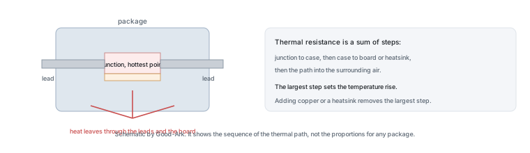 Why Do Diodes Get Hot? Forward Voltage, Current, and Heat for BeginnersKnowledge
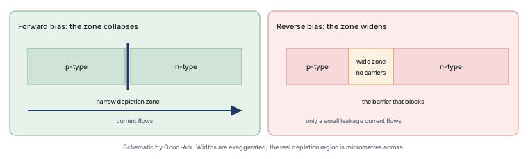 How Does a Diode Work? The PN Junction in Plain LanguageKnowledge
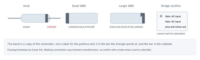 Diode Anode and Cathode: How to Tell Which End Is Which Every TimeKnowledge
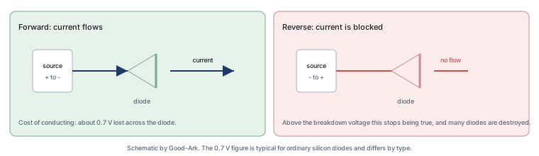 What Is a Diode? The One-Way Valve of Electronics, Explained With Everyday PicturesKnowledge
 Why 800 V Electric Cars Need Silicon CarbideKnowledge
 Wide-Bandgap Semiconductors Explained in One SittingKnowledge